Toyota Yaris: Steering Pad Switch / Inspection
INSPECTION
PROCEDURE
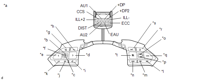
1. INSPECT STEERING PAD SWITCH ASSEMBLY (w/ Dynamic Radar Cruise Control System)
(a) Check the resistance.
(1) Measure the resistance according to the value(s) in the table below.

| *a | Component without harness connected (Steering Pad Switch Assembly) | *b | Up |
| *c | Down | *d | Right |
| *e | Left | *f | OK |
| *g | Back | *h | On/off Hook |
| *i | Voice | *j | Volume+ |
| *k | Volume- | *l | Seek+ |
| *m | Seek- | *n | MODE |
| *o | +RES | *p | -SET |
| *q | CANCEL | *r | Lane Tracing Assist |
| *s | Distance Control | *t | Cruise Control Main |
Standard Resistance:
| Tester Connection | Condition | Specified Condition |
|---|---|---|
| 3 (AU1) - 10 (EAU) | No switch pushed | 95 to 105 kΩ |
| 3 (AU1) - 10 (EAU) | Seek+ switch pushed | Below 2.5 Ω |
| 3 (AU1) - 10 (EAU) | Seek- switch pushed | 313 to 345 Ω |
| 3 (AU1) - 10 (EAU) | Volume+ switch pushed | 950 to 1050 Ω |
| 3 (AU1) - 10 (EAU) | Volume- switch pushed | 2955 to 3265 Ω |
| 9 (AU2) - 10 (EAU) | No switch pushed | 95 to 105 kΩ |
| 9 (AU2) - 10 (EAU) | MODE switch pushed | Below 2.5 Ω |
| 9 (AU2) - 10 (EAU) | On/off hook switch pushed | 950 to 1050 Ω |
| 9 (AU2) - 10 (EAU) | Voice switch pushed | 2955 to 3265 Ω |
| 5 (+DP2) - 10 (EAU) | No switch pushed | 95 to 105 kΩ |
| 5 (+DP2) - 10 (EAU) | Left switch pushed | Below 2.5 Ω |
| 5 (+DP2) - 10 (EAU) | Up switch pushed | 313 to 345 Ω |
| 5 (+DP2) - 10 (EAU) | Down switch pushed | 950 to 1050 Ω |
| 5 (+DP2) - 10 (EAU) | Right switch pushed | 2955 to 3265 Ω |
| 4 (+DP) - 10 (EAU) | No switch pushed | 95 to 105 kΩ |
| 4 (+DP) - 10 (EAU) | OK switch pushed | Below 2.5 Ω |
| 4 (+DP) - 10 (EAU) | Back switch pushed | 313 to 345 Ω |
| 8 (DIST) - 12 (ECC) | No switch pushed | 1 MΩ or higher |
| 8 (DIST) - 12 (ECC) | Distance control switch pushed | Below 2.5 Ω |
| 8 (DIST) - 12 (ECC) | Lane tracing assist switch pushed | 228 to 252 Ω |
| 2 (CCS) - 12 (ECC) | No switch pushed | 1 MΩ or higher |
| 2 (CCS) - 12 (ECC) | Cruise control main switch pushed | Below 2.5 Ω |
| 2 (CCS) - 12 (ECC) | CANCEL switch pushed | 228 to 252 Ω |
| 2 (CCS) - 12 (ECC) | +RES switch pushed | 599 to 661 Ω |
| 2 (CCS) - 12 (ECC) | -SET switch pushed | 1463 to 1617 Ω |
If the result is not as specified, replace the steering pad switch assembly.
(b) Check the illumination.
(1) Apply auxiliary battery voltage to the steering pad switch assembly and check that the illumination.
OK:
| Tester Connection | Condition | Specified Condition |
|---|---|---|
| 1 (ILL+2) - 6 (ILL-) | 1 (ILL+2) - Auxiliary battery positive (+) 6 (ILL-) - Auxiliary battery negative (-) | Illumination illuminates |
If the result is not as specified, replace the steering pad switch assembly.
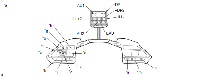
2. INSPECT STEERING PAD SWITCH ASSEMBLY (w/o Dynamic Radar Cruise Control System)
(a) Check the resistance.
(1) Measure the resistance according to the value(s) in the table below.

| *a | Component without harness connected (Steering Pad Switch Assembly) | *b | Up |
| *c | Down | *d | Right |
| *e | Left | *f | OK |
| *g | Back | *h | On/off Hook |
| *i | Voice | *j | Volume+ |
| *k | Volume- | *l | Seek+ |
| *m | Seek- | *n | MODE |
Standard Resistance:
| Tester Connection | Condition | Specified Condition |
|---|---|---|
| 3 (AU1) - 10 (EAU) | No switch pushed | 95 to 105 kΩ |
| 3 (AU1) - 10 (EAU) | Seek+ switch pushed | Below 2.5 Ω |
| 3 (AU1) - 10 (EAU) | Seek- switch pushed | 313 to 345 Ω |
| 3 (AU1) - 10 (EAU) | Volume+ switch pushed | 950 to 1050 Ω |
| 3 (AU1) - 10 (EAU) | Volume- switch pushed | 2955 to 3265 Ω |
| 9 (AU2) - 10 (EAU) | No switch pushed | 95 to 105 kΩ |
| 9 (AU2) - 10 (EAU) | MODE switch pushed | Below 2.5 Ω |
| 9 (AU2) - 10 (EAU) | On/off hook switch pushed | 950 to 1050 Ω |
| 9 (AU2) - 10 (EAU) | Voice switch pushed | 2955 to 3265 Ω |
| 5 (+DP2) - 10 (EAU) | No switch pushed | 95 to 105 kΩ |
| 5 (+DP2) - 10 (EAU) | Left switch pushed | Below 2.5 Ω |
| 5 (+DP2) - 10 (EAU) | Up switch pushed | 313 to 345 Ω |
| 5 (+DP2) - 10 (EAU) | Down switch pushed | 950 to 1050 Ω |
| 5 (+DP2) - 10 (EAU) | Right switch pushed | 2955 to 3265 Ω |
| 4 (+DP) - 10 (EAU) | No switch pushed | 95 to 105 kΩ |
| 4 (+DP) - 10 (EAU) | OK switch pushed | Below 2.5 Ω |
| 4 (+DP) - 10 (EAU) | Back switch pushed | 313 to 345 Ω |
If the result is not as specified, replace the steering pad switch assembly.
(b) Check the illumination.
(1) Apply auxiliary battery voltage to the steering pad switch assembly and check that the illumination.
OK:
| Tester Connection | Condition | Specified Condition |
|---|---|---|
| 1 (ILL+2) - 6 (ILL-) | 1 (ILL+2) - Auxiliary battery positive (+) 6 (ILL-) - Auxiliary battery negative (-) | Illumination illuminates |
If the result is not as specified, replace the steering pad switch assembly.
 Removal
REMOVAL CAUTION / NOTICE / HINT HINT: When the cable is disconnected/reconnected to the auxiliary battery terminal, systems temporarily stop operating...
 Installation
INSTALLATION PROCEDURE 1. INSTALL STEERING PAD SWITCH ASSEMBLY (a) Engage the 6 pins to install the steering pad switch assembly. (b) Connect the steering pad switch connector to the spiral cable sub-assembly...
Other information:
Toyota Yaris XP210 (2020-2026) Reapir and Service Manual: Wireless Door Lock Tuner Component Internal Failure (B124296)
DESCRIPTION The smart door control receiver assembly is used to receive radio waves related to the entry functions of the electrical key transmitter sub-assembly. The certification ECU (smart key ECU assembly) decodes the requested electrical key transmitter sub-assembly operation by identifying a key code based on the radio waves received via the smart door control receiver assembly...
Toyota Yaris XP210 (2020-2026) Reapir and Service Manual: On-vehicle Inspection
ON-VEHICLE INSPECTION PROCEDURE 1. INSPECT AIR CONDITIONING PRESSURE SENSOR (a) Check the wire harness. (1) Disconnect the A51 air conditioner pressure sensor connector. (2) Disconnect the H25 air conditioning amplifier assembly connector. (3) Measure the resistance according to the value(s) in the table below...
Categories
- Manuals Home
- Toyota Yaris Owners Manual
- Toyota Yaris Service Manual
- Brake System Control Module "A" System Voltage System Voltage Low (C137BA2)
- Immobilizer System
- Power Integration No.1 System Missing Message (B235287,B235587,B235787-B235987)
- New on site
- Most important about car
Fuel-Filler Lid and Cap
WARNING
When removing the fuel-filler cap, loosen the cap slightly and wait for any hissing to stop, then remove it
Fuel spray is dangerous. Fuel can burn skin and eyes and cause illness if ingested. Fuel spray is released when there is pressure in the fuel tank and the fuel-filler cap is removed too quickly.
