Toyota Yaris: Vehicle Stability Control System / Right Rear Wheel Speed Sensor Circuit Short to Ground or Open (C051214)
DESCRIPTION
Refer to DTC C05121F.
Click here

| DTC No. | Detection Item | DTC Detection Condition | Trouble Area | DTC Output from |
|---|---|---|---|---|
| C051214 | Right Rear Wheel Speed Sensor Circuit Short to Ground or Open | An open in the speed sensor signal circuit continues for 0.5 seconds or more. |
| Brake |
WIRING DIAGRAM
Refer to DTC C05121F.
Click here

CAUTION / NOTICE / HINT
NOTICE:
-
After replacing the skid control ECU (brake actuator assembly), perform "Calibration".
Click here

-
After replacing or removing and installing a speed sensor, perform Dealer Mode (Signal Check) inspection to confirm that the speed sensors are operating correctly.
Click here

PROCEDURE
| 1. | READ VALUE USING GTS (RR SPEED OPEN) |
(a) Operate the GTS to check the Data List.
Chassis > Brake > Data List| Tester Display | Measurement Item | Range | Normal Condition | Diagnostic Note |
|---|---|---|---|---|
| RR Speed Open | Rear speed sensor RH open detection | Under intermittent / Normal | Under intermittent: Momentary interruption detected Normal: Momentary interruption not detected | - |
| Tester Display |
|---|
| RR Speed Open |
(b) Select the line graph display.
(c) Check for any momentary interruption in the wire harness and connector.
Click here

OK:
Normal (There are no momentary interruptions.)
NOTICE:
Perform the above inspection before removing the sensor and connector.
| NG |
 | GO TO STEP 5 |
|

| 2. | READ VALUE USING GTS (RR WHEEL SPEED) |
(a) Operate the GTS to check the Data List.
Chassis > Brake > Data List| Tester Display | Measurement Item | Range | Normal Condition | Diagnostic Note |
|---|---|---|---|---|
| RR Wheel Speed | Rear wheel speed sensor RH reading | Min.: 0.0 km/h (0.0 mph) Max.: 6553.5 km/h (4072 mph) | Vehicle stopped: 0.0 km/h (0.0 mph) | When driving at constant speed: No large fluctuations |
| Tester Display |
|---|
| RR Wheel Speed |
(b) Drive the vehicle and perform a road test.
(c) Check the speed value output from the speed sensor displayed on the GTS.
HINT:
Factors that affect the indicated vehicle speed include tire size, tire pressure, and tire wear. The speed indicated on the speedometer has an allowable margin of error. This can be tested using a speedometer tester (calibrated chassis dynamometer). For details about testing and the margin of error, see the reference chart.
Click here

OK:
The speed value output from the speed sensor displayed on the GTS is similar to the speed indicated on the speedometer.
| NG |
 | GO TO STEP 5 |
|

| 3. | CLEAR DTC |
(a) Operate the GTS to clear the codes.
Chassis > Brake > Clear DTCs(b) Press the DTC clear button.
(c) Turn the ignition switch off.
|

| 4. | RECONFIRM DTC |
(a) Based on the Freeze Frame Data and interview with the customer, attempt to reproduce the conditions when the malfunction occurred.
(b) Operate the GTS to read the DTCs.
Chassis > Brake > Trouble Codes(c) Check if the same DTC is output.
| Result | Proceed to |
|---|---|
| C051214 is not output | A |
| C051214 is output | B |
| A |
 | USE SIMULATION METHOD TO CHECK |
| B |
 | REPLACE BRAKE ACTUATOR ASSEMBLY |
| 5. | CHECK HARNESS AND CONNECTOR (REAR SPEED SENSOR RH - BRAKE ACTUATOR ASSEMBLY) |
(a) Make sure that there is no looseness at the locking part and the connecting part of the connectors.
OK:
The connector is securely connected.
(b) Disconnect the A108 skid control ECU (brake actuator assembly) connector.
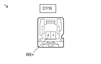
(c) Disconnect the O116 rear speed sensor RH connector.
(d) Check both the connector case and the terminals for deformation and corrosion.
OK:
No deformation or corrosion.
(e) Measure the resistance according to the value(s) in the table below.
Standard Resistance:
| Tester Connection | Condition | Specified Condition |
|---|---|---|
| O116-2 (RR+) - A108-16 (RR+) | Always | Below 1 Ω |
| O116-2 (RR+) or A108-16 (RR+) - Body ground | Always | 10 kΩ or higher |
| O116-1 (RR-) - A108-15 (RR-) | Always | Below 1 Ω |
| O116-1 (RR-) or A108-15 (RR-) - Body ground | Always | 10 kΩ or higher |
| NG |
 | REPAIR OR REPLACE HARNESS OR CONNECTOR |
|

| 6. | INSPECT BRAKE ACTUATOR ASSEMBLY (SENSOR POWER SOURCE CIRCUIT) |
(a) Reconnect the A108 skid control ECU (brake actuator assembly) connector.
| (b) Make sure that there is no looseness at the locking part and the connecting part of the connectors. OK: The connector is securely connected. |
|
(c) Turn the ignition switch to ON.
(d) Measure the voltage according to the value(s) in the table below.
Standard Voltage:
| Tester Connection | Condition | Specified Condition |
|---|---|---|
| O116-2 (RR+) - Body ground | Ignition switch ON | 11 to 14 V |
| OK |
 | REPLACE REAR SPEED SENSOR RH |
| NG |
 | REPLACE BRAKE ACTUATOR ASSEMBLY |
 Right Rear Wheel Speed Sensor Circuit Short to Battery (C051212)
DESCRIPTION Refer to DTC C05121F. Click here
DTC No. Detection Item DTC Detection Condition Trouble Area DTC Output from C051212 Right Rear Wheel Speed Sensor Circuit Short to Battery The speed sensor short signal is ON continuously for 0...
 Right Rear Wheel Speed Sensor Circuit Intermittent (C05121F)
DESCRIPTION The speed sensor detects wheel speed and sends the appropriate signals to the skid control ECU (brake actuator assembly). These signals are used for brake control...
Other information:
Toyota Yaris XP210 (2020-2025) Owner's Manual: Vehicle Loading
This section will guide you in the proper loading of your vehicle, to keep your loaded vehicle weight within its design rating capability. Properly loading your vehicle will provide maximum return of vehicle design performance. Before loading your vehicle, familiarize yourself with the following terms for determining your vehicle’s weight ratings, from the vehicle’s Safety Certification Label and Tire and Load Information Label: Base Curb Weight is the weight of the vehicle including a full tank of fuel and all standard equipment...
Toyota Yaris XP210 (2020-2025) Reapir and Service Manual: Relay
On-vehicle InspectionON-VEHICLE INSPECTION PROCEDURE 1. INSPECT HORN RELAY ASSEMBLY (a) Check the resistance. (1) Measure the resistance according to the value(s) in the table below. Standard Resistance: Tester Connection Condition Specified Condition 3 - 5 Auxiliary battery voltage not applied between terminals 1 and 2 10 kΩ or higher 3 - 5 Auxiliary battery voltage applied between terminals 1 and 2 Below 1 Ω If the result is not as specified, replace the horn relay assembly...
Categories
- Manuals Home
- Toyota Yaris Owners Manual
- Toyota Yaris Service Manual
- Removal
- To Set Speed
- Immobilizer System
- New on site
- Most important about car
Front Seat Belt Pretensioners
The front seat belt pretensioners are designed to deploy in moderate or severe frontal, near frontal collisions.
In addition, the pretensioners operate when a side collision or a rollover accident is detected. The pretensioners operate differently depending on what types of air bags are equipped. For more details about the seat belt pretensioner operation, refer to the SRS Air Bag Deployment Criteria.