Toyota Yaris: Vehicle Stability Control System / Right Rear Wheel Speed Sensor Circuit Intermittent (C05121F)
DESCRIPTION
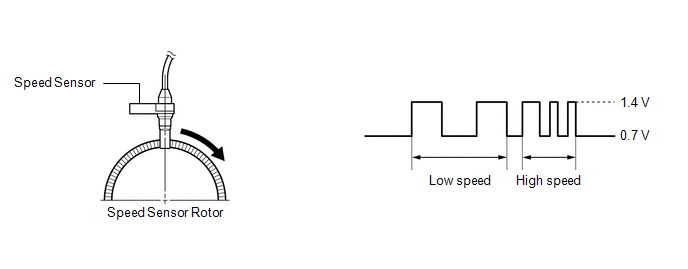
The speed sensor detects wheel speed and sends the appropriate signals to the skid control ECU (brake actuator assembly). These signals are used for brake control.
Speed sensor rotors have rows of alternating N and S magnetic poles, and their magnetic fields change when the rotors turn.
Each speed sensor detects that magnetic change and sends a pulse signal to the skid control ECU (brake actuator assembly).
HINT:
When the connectors between the speed sensor and skid control ECU (brake actuator assembly) are connected, the following waveform is output.
| DTC No. | Detection Item | DTC Detection Condition | Trouble Area | DTC Output from |
|---|---|---|---|---|
| C05121F | Right Rear Wheel Speed Sensor Circuit Intermittent | Any of the following is detected:
|
| Brake |
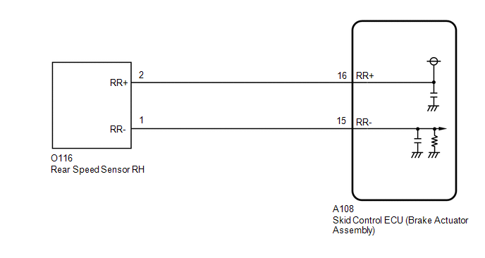
WIRING DIAGRAM
CAUTION / NOTICE / HINT
NOTICE:
-
After replacing the skid control ECU (brake actuator assembly), perform "Calibration".
Click here

-
After replacing or removing and installing a speed sensor, perform Dealer Mode (Signal Check) inspection to confirm that the speed sensors are operating correctly.
Click here

-
After replacing or removing and installing a speed sensor rotor, perform Dealer Mode (Signal Check) inspection to confirm that the speed sensors are operating correctly.
Click here

PROCEDURE
| 1. | READ VALUE USING GTS (RR SPEED SENSOR VOLTAGE OPEN) |
(a) Operate the GTS to check the Data List.
Chassis > Brake > Data List| Tester Display | Measurement Item | Range | Normal Condition | Diagnostic Note |
|---|---|---|---|---|
| RR Speed Sensor Voltage Open | Rear speed sensor RH voltage open detection | Under intermittent / Normal | Under intermittent: Momentary interruption detected Normal: Momentary interruption not detected | - |
| Tester Display |
|---|
| RR Speed Sensor Voltage Open |
(b) Select the line graph display.
(c) Check for any momentary interruption in the wire harness and connector.
Click here

OK:
Normal (There are no momentary interruptions.)
NOTICE:
Perform the above inspection before removing the sensor and connector.
| NG |
 | GO TO STEP 5 |
|

| 2. | READ VALUE USING GTS (RR WHEEL SPEED) |
(a) Operate the GTS to check the Data List.
Chassis > Brake > Data List| Tester Display | Measurement Item | Range | Normal Condition | Diagnostic Note |
|---|---|---|---|---|
| RR Wheel Speed | Rear wheel speed sensor RH reading | Min.: 0.0 km/h (0.0 mph) Max.: 6553.5 km/h (4072 mph) | Vehicle stopped: 0.0 km/h (0.0 mph) | When driving at constant speed: No large fluctuations |
| Tester Display |
|---|
| RR Wheel Speed |
(b) Drive the vehicle and perform a road test.
(c) Check the speed value output from the speed sensor displayed on the GTS.
HINT:
Factors that affect the indicated vehicle speed include tire size, tire pressure, and tire wear. The speed indicated on the speedometer has an allowable margin of error. This can be tested using a speedometer tester (calibrated chassis dynamometer). For details about testing and the margin of error, see the reference chart.
Click here

OK:
The speed value output from the speed sensor displayed on the GTS is similar to the speed indicated on the speedometer.
| NG |
 | GO TO STEP 5 |
|

| 3. | CLEAR DTC |
(a) Operate the GTS to clear the codes.
Chassis > Brake > Clear DTCs(b) Press the DTC clear button.
(c) Turn the ignition switch off.
|

| 4. | RECONFIRM DTC |
(a) Based on the Freeze Frame Data and interview with the customer, attempt to reproduce the conditions when the malfunction occurred.
(b) Operate the GTS to read the DTCs.
Chassis > Brake > Trouble Codes(c) Check if the same DTC is output.
| Result | Proceed to |
|---|---|
| C05121F is not output | A |
| C05121F is output | B |
| A |
 | USE SIMULATION METHOD TO CHECK |
| B |
 | REPLACE BRAKE ACTUATOR ASSEMBLY |
| 5. | CHECK REAR SPEED SENSOR RH INSTALLATION |
| (a) Turn the ignition switch off. |
|
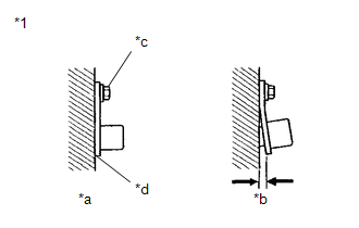
(b) Check the rear speed sensor RH installation.
OK:
There is no clearance between the rear speed sensor RH and rear axle carrier sub-assembly RH.
The installation bolt is tightened properly.
Torque
8.5 N*m (87 kgf*cm, 75 in.*lbf)
| NG |
 | REINSTALL OR REPLACE REAR SPEED SENSOR RH |
|

| 6. | CHECK REAR SPEED SENSOR RH AND REAR SPEED SENSOR ROTOR RH (CHECK FOR FOREIGN MATTER) |
(a) Remove the rear speed sensor RH and the component with the rear speed sensor rotor RH.
for rear speed sensor RH: Click here

for rear speed sensor rotor RH: Click here

(b) Check the rear speed sensor RH tip and rear speed sensor rotor RH.
OK:
No scratches, oil, or foreign matter on the rear speed sensor RH tip and rear speed sensor rotor RH.
NOTICE:
- If there is oil or foreign matter on the rear speed sensor RH, clean the rear speed sensor RH.
- If the rear speed sensor RH is damaged, replace the rear speed sensor RH with a new one.
- Do not use parts cleaner when cleaning the rear speed sensor rotor RH.
- If the rear speed sensor rotor RH is damaged, replace the rear speed sensor rotor RH with a new one.
HINT:
- The rear speed sensor rotor RH is incorporated into the rear axle hub and bearing assembly RH.
- If the rear speed sensor rotor RH needs to be replaced, replace it together with the rear axle hub and bearing assembly RH.
| NG |
 | CLEAN OR REPLACE REAR SPEED SENSOR RH OR COMPONENT WITH REAR SENSOR ROTOR RH |
|

| 7. | CHECK HARNESS AND CONNECTOR (REAR SPEED SENSOR RH - BRAKE ACTUATOR ASSEMBLY) |
(a) Make sure that there is no looseness at the locking part and the connecting part of the connectors.
OK:
The connector is securely connected.
(b) Disconnect the A108 skid control ECU (brake actuator assembly) connector.
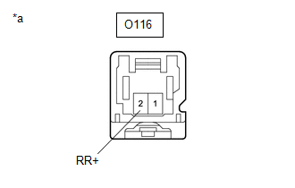
(c) Disconnect the O116 rear speed sensor RH connector.
(d) Check both the connector case and the terminals for deformation and corrosion.
OK:
No deformation or corrosion.
(e) Measure the resistance according to the value(s) in the table below.
Standard Resistance:
| Tester Connection | Condition | Specified Condition |
|---|---|---|
| O116-2 (RR+) - A108-16 (RR+) | Always | Below 1 Ω |
| O116-2 (RR+) or A108-16 (RR+) - Body ground | Always | 10 kΩ or higher |
| O116-1 (RR-) - A108-15 (RR-) | Always | Below 1 Ω |
| O116-1 (RR-) or A108-15 (RR-) - Body ground | Always | 10 kΩ or higher |
| NG |
 | REPAIR OR REPLACE HARNESS OR CONNECTOR |
|

| 8. | INSPECT BRAKE ACTUATOR ASSEMBLY (SENSOR POWER SOURCE CIRCUIT) |
(a) Reconnect the A108 skid control ECU (brake actuator assembly) connector.
| (b) Make sure that there is no looseness at the locking part and the connecting part of the connectors. OK: The connector is securely connected. |
|
(c) Turn the ignition switch to ON.
(d) Measure the voltage according to the value(s) in the table below.
Standard Voltage:
| Tester Connection | Condition | Specified Condition |
|---|---|---|
| O116-2 (RR+) - Body ground | Ignition switch ON | 11 to 14 V |
| OK |
 | REPLACE REAR SPEED SENSOR RH |
| NG |
 | REPLACE BRAKE ACTUATOR ASSEMBLY |
 Right Rear Wheel Speed Sensor Circuit Short to Ground or Open (C051214)
DESCRIPTION Refer to DTC C05121F. Click here
DTC No. Detection Item DTC Detection Condition Trouble Area DTC Output from C051214 Right Rear Wheel Speed Sensor Circuit Short to Ground or Open An open in the speed sensor signal circuit continues for 0...
 Multi-axis Acceleration Sensor Module "A" Missing Calibration (C051D54,C121054)
DESCRIPTION The airbag sensor assembly has a built-in yaw rate and acceleration sensor and detects the vehicle condition. The skid control ECU (brake actuator assembly) receives signals from the yaw rate and acceleration sensor (airbag sensor assembly) via CAN communication...
Other information:
Toyota Yaris XP210 (2020-2026) Reapir and Service Manual: Data List / Active Test
DATA LIST / ACTIVE TEST DATA LIST NOTICE: In the table below, the values listed under "Normal Condition" are reference values. Do not depend solely on these reference values when deciding whether a part is faulty or not. HINT: Using the GTS to read the Data List allows the values or states of switches, sensors, actuators and other items to be read without removing any parts...
Toyota Yaris XP210 (2020-2026) Reapir and Service Manual: Problem Symptoms Table
PROBLEM SYMPTOMS TABLE NOTICE: Use the table below to help determine the cause of problem symptoms. If multiple suspected areas are listed, the potential causes of the symptoms are listed in order of probability in the "Suspected Area" column of the table...
Categories
- Manuals Home
- Toyota Yaris Owners Manual
- Toyota Yaris Service Manual
- Fuel Gauge
- Opening and Closing the Liftgate/Trunk Lid
- G16e-gts (engine Mechanical)
- New on site
- Most important about car
Keys

To use the auxiliary key, press the knob and pull out the auxiliary key from the smart key.
