Toyota Yaris: Vehicle Stability Control System / Right Front Wheel Speed Sensor Signal Stuck Low (C050623)
DESCRIPTION
Refer to DTC C05061F.
Click here

| DTC No. | Detection Item | DTC Detection Condition | Trouble Area | DTC Output from |
|---|---|---|---|---|
| C050623 | Right Front Wheel Speed Sensor Signal Stuck Low | Any of the following is detected:
|
| Brake |
WIRING DIAGRAM
Refer to DTC C05061F.
Click here

CAUTION / NOTICE / HINT
NOTICE:
-
After replacing or removing and installing a speed sensor, perform Dealer Mode (Signal Check) inspection to confirm that the speed sensors are operating correctly.
Click here

-
After replacing or removing a speed sensor rotor, perform Dealer Mode (Signal Check) inspection to confirm that the speed sensors are operating correctly.
Click here

PROCEDURE
| 1. | CHECK FRONT SPEED SENSOR RH INSTALLATION |
| (a) Turn the ignition switch off. |
|
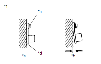
(b) Check the front speed sensor RH installation.
OK:
There is no clearance between the front speed sensor RH and front axle carrier sub-assembly.
The installation bolt is tightened properly.
Torque
8.5 N*m (87 kgf*cm, 75 in.*lbf)
| NG |
 | REINSTALL OR REPLACE FRONT SPEED SENSOR RH |
|

| 2. | CHECK FRONT SPEED SENSOR RH (CHECK FOR FOREIGN MATTER) |
(a) Remove the front speed sensor RH.
Click here

(b) Check the front speed sensor RH tip.
OK:
The front speed sensor RH tip is free of scratches, oil, and foreign matter.
NOTICE:
- If there is oil or foreign matter on the front speed sensor RH, clean the front speed sensor RH.
- If the front speed sensor RH is damaged, replace the front speed sensor RH with a new one.
| NG |
 | CLEAN OR REPLACE FRONT SPEED SENSOR RH |
|

| 3. | READ VALUE USING GTS (FR WHEEL SPEED) |
(a) Operate the GTS to check the Data List.
Chassis > Brake > Data List| Tester Display | Measurement Item | Range | Normal Condition | Diagnostic Note |
|---|---|---|---|---|
| FR Wheel Speed | Front wheel speed sensor RH reading | Min.: 0.0 km/h (0.0 mph) Max.: 6553.5 km/h (4072 mph) | Vehicle stopped: 0.0 km/h (0.0 mph) | When driving at constant speed: No large fluctuations |
| Tester Display |
|---|
| FR Wheel Speed |
(b) Drive the vehicle and perform a road test.
(c) Check the speed value output from the speed sensor displayed on the GTS.
HINT:
Factors that affect the indicated vehicle speed include tire size, tire pressure, and tire wear. The speed indicated on the speedometer has an allowable margin of error. This can be tested using a speedometer tester (calibrated chassis dynamometer). For details about testing and the margin of error, see the reference chart.
Click here

OK:
The speed value output from the speed sensor displayed on the GTS is similar to the speed indicated on the speedometer.
| OK |
 | USE SIMULATION METHOD TO CHECK |
|

| 4. | CHECK HARNESS AND CONNECTOR (FRONT SPEED SENSOR RH - BRAKE ACTUATOR ASSEMBLY) |
(a) Turn the ignition switch off.
(b) Make sure that there is no looseness at the locking part and the connecting part of the connectors.
OK:
The connector is securely connected.
(c) Disconnect the A108 skid control ECU (brake actuator assembly) connector.
(d) Disconnect the A23 front speed sensor RH connector.
(e) Check both the connector case and the terminals for deformation and corrosion.
OK:
No deformation or corrosion.
(f) Measure the resistance according to the value(s) in the table below.
Standard Resistance:
| Tester Connection | Condition | Specified Condition |
|---|---|---|
| A23-1 (FR+) - A108-31 (FR+) | Always | Below 1 Ω |
| A23-1 (FR+) or A108-31 (FR+) - Body ground | Always | 10 kΩ or higher |
| A23-2 (FR-) - A108-30 (FR-) | Always | Below 1 Ω |
| A23-2 (FR-) or A108-30 (FR-) - Body ground | Always | 10 kΩ or higher |
| NG |
 | REPAIR OR REPLACE HARNESS OR CONNECTOR |
|

| 5. | CHECK FRONT SPEED SENSOR ROTOR RH (CHECK FOR FOREIGN MATTER) |
(a) Remove the component with the front speed sensor rotor RH.
Click here

(b) Check the front speed sensor rotor RH.
OK:
The front speed sensor rotor RH is free of scratches, oil, and foreign matter.
NOTICE:
- If there is oil or foreign matter on the front speed sensor rotor RH, clean the front speed sensor rotor RH.
- Do not use parts cleaner when cleaning the front speed sensor rotor RH.
- If the front speed sensor rotor RH is damaged, replace the front speed sensor rotor RH with a new one.
HINT:
- The front speed sensor rotor RH is incorporated into the front axle hub sub-assembly RH.
- If the front speed sensor rotor RH needs to be replaced, replace it together with the front axle hub sub-assembly RH.
| Result | Proceed to |
|---|---|
| OK | A |
| NG (The front speed sensor rotor RH is damaged.) | B |
| NG (There is foreign matter on the front speed sensor rotor RH.) | C |
| A |
 | REPLACE FRONT SPEED SENSOR RH |
| B |
 | REPLACE FRONT AXLE HUB SUB-ASSEMBLY RH |
| C |
 | CLEAN FRONT SPEED SENSOR ROTOR RH |
 Right Front Wheel Speed Sensor Circuit Intermittent (C05061F)
DESCRIPTION The speed sensor detects wheel speed and sends the appropriate signals to the skid control ECU (brake actuator assembly). These signals are used for brake control...
 Left Rear Wheel Speed Sensor Circuit Short to Battery (C050C12)
DESCRIPTION Refer to DTC C050C1F. Click here
DTC No. Detection Item DTC Detection Condition Trouble Area DTC Output from C050C12 Left Rear Wheel Speed Sensor Circuit Short to Battery The speed sensor short signal is ON continuously for 0...
Other information:
Toyota Yaris XP210 (2020-2026) Reapir and Service Manual: Utility
UTILITY Recognition Camera/Target Position Memory HINT: Recognition Camera/Target Position Memory is used to enter required information into the forward recognition camera. (a) Perform Recognition Camera/Target Position Memory according to the display on the GTS...
Toyota Yaris XP210 (2020-2026) Reapir and Service Manual: Utility
U..
Categories
- Manuals Home
- Toyota Yaris Owners Manual
- Toyota Yaris Service Manual
- To Set Speed
- Engine & Hybrid System
- Diagnostic Trouble Code Chart
- New on site
- Most important about car
Refueling
Before refueling, close all the doors, windows, and the liftgate/trunk lid, and switch the ignition OFF.
To open the fuel-filler lid, pull the remote fuel-filler lid release.
