Toyota Yaris: G16e-gts (emission Control) / Emission Control System
Parts Location
PARTS LOCATION
ILLUSTRATION
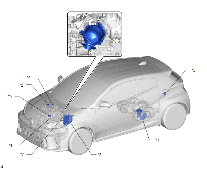
| *1 | CANISTER (CHARCOAL CANISTER ASSEMBLY) | *2 | VACUUM REGULATING VALVE ASSEMBLY |
| *3 | FUEL TANK CAP ASSEMBLY | *4 | PCV VALVE (VENTILATION VALVE SUB-ASSEMBLY) |
| *5 | PURGE VALVE (PURGE VSV) | *6 | E.F.I. VACUUM SENSOR ASSEMBLY (MANIFOLD ABSOLUTE PRESSURE SENSOR) |
| *7 | ECM | *8 | NO. 1 ENGINE ROOM RELAY BLOCK - EFI-MAIN NO. 1 RELAY - EFI-MAIN NO. 2 RELAY - EFI-MAIN NO. 1 FUSE - EFI-MAIN NO. 2 FUSE - EFI NO. 4 FUSE |
| *9 | VACUUM SENSOR ASSEMBLY | - | - |
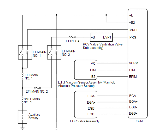
System Diagram
SYSTEM DIAGRAM
On-vehicle Inspection
ON-VEHICLE INSPECTION
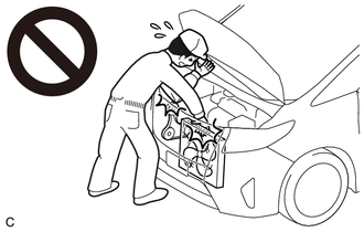
CAUTION / NOTICE / HINT
CAUTION:
- When working near the engine room while the engine has started or the power source mode is ignition switch to ON (IG), do not touch the fan and generator V belt or rotating components such as the fan, etc.
- Touching the fan and generator V belt or rotating components such as the fan, etc. could result in your hand or clothing getting caught and pulled in.
PROCEDURE
1. VISUALLY INSPECT HOSES, CONNECTIONS AND GASKETS
(a) Visually check that the hoses, connections and gaskets have no cracks, leaks or damage.
NOTICE:
- Detachment or other problems with the engine oil dipstick, filler cap, ventilation hose or other components may cause the engine to run improperly.
- Air suction caused by disconnections, looseness or cracks in any part of the air induction system between the throttle body assembly and cylinder head sub-assembly will cause engine failure or engine malfunctions.
If any defects are found, replace parts as necessary.
2. INSPECT EVAPORATIVE EMISSION CONTROL SYSTEM
CAUTION:
- When working near the engine room while the engine has started or the power source mode is ignition switch to ON (IG), do not touch the fan and generator V belt or rotating components such as the fan, etc.
- Touching the fan and generator V belt or rotating components such as the fan, etc. could result in your hand or clothing getting caught and pulled in.
(a) Connect the GTS to the DLC3.
(b) Start the engine.
(c) Warm up the engine.
(d) Turn the GTS on.
(e) Slide the clip and disconnect the fuel vapor feed hose from the purge valve (purge VSV).
(f) Enter the following menus: Powertrain / Engine and ECT / Active Test / Activate the EVAP Purge VSV.
Powertrain > Engine > Active Test| Tester Display |
|---|
| Activate the EVAP Purge VSV |
(g) Check that vacuum occurs at the purge valve (purge VSV) port.
(h) If vacuum does not occur, check the following items:
- Purge valve (purge VSV)
- Clogs in the fuel vapor feed hose that connects the intake manifold and purge valve (purge VSV)
-
Voltage from the ECM PRG terminal
Click here

(i) Exit Active Test mode and connect the fuel vapor feed hose and slide the clip to secure it.
(j) Enter the following menus: Powertrain / Engine and ECT / Data List / EVAP Purge VSV.
Powertrain > Engine > Data List| Tester Display |
|---|
| EVAP (Purge) VSV |
(k) Warm up the engine and drive the vehicle.
(l) Confirm that the purge valve (purge VSV) opens.
If the result is not as specified, replace the purge valve (purge VSV), wire harness or ECM.
 Installation
INSTALLATION PROCEDURE 1. INSTALL FUEL MAIN VALVE ASSEMBLY Click here
2. INSTALL FUEL PUMP Click here
3. INSTALL FUEL SENDER GAUGE ASSEMBLY Click here
4...
 Fuel Tank Cap
InspectionINSPECTION PROCEDURE 1. INSPECT FUEL TANK CAP ASSEMBLY (a) Visually check that the fuel tank cap assembly and gasket are not deformed or damaged...
Other information:
Toyota Yaris XP210 (2020-2026) Reapir and Service Manual: Reassembly
REASSEMBLY PROCEDURE 1. INSTALL FRONT BUMPER LOWER ABSORBER (a) Install the 4 grommets. (b) Engage the claws to install the front bumper lower absorber. (c) Install the clip and 5 screws. 2. INSTALL NO. 1 ENGINE UNDER COVER ASSEMBLY Click here 3...
Toyota Yaris XP210 (2020-2026) Reapir and Service Manual: How To Proceed With Troubleshooting
CAUTION / NOTICE / HINT HINT: Use these procedures to troubleshoot the power integration system. *: Use the GTS. PROCEDURE 1. VEHICLE BROUGHT TO WORKSHOP NEXT 2. INSPECT AUXILIARY BATTERY VOLTAGE (a) Measure the auxiliary battery voltage with the ignition switch off...
Categories
- Manuals Home
- Toyota Yaris Owners Manual
- Toyota Yaris Service Manual
- Maintenance
- Battery Monitor Module General Electrical Failure (P058A01)
- Headlights
- New on site
- Most important about car
Supplemental Restraint System (SRS) Precautions
The front and side supplemental restraint systems (SRS) include different types of air bags. Please verify the different types of air bags which are equipped on your vehicle by locating the “SRS AIRBAG” location indicators. These indicators are visible in the area where the air bags are installed.
The air bags are installed in the following locations:
The steering wheel hub (driver air bag) The front passenger dashboard (front passenger air bag) The outboard sides of the front seatbacks (side air bags) The front and rear window pillars, and the roof edge along both sides (curtain air bags)