Toyota Yaris: Front Bumper / Removal
REMOVAL
PROCEDURE
1. REMOVE PIN HOLD CLIP
(a) Apply protective tape around the front bumper assembly.
HINT:
Use the same procedure for the RH side and LH side.
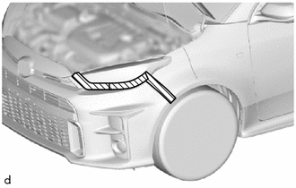
.png) | Protective Tape |
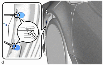
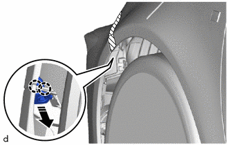
| (b) Using a screwdriver with its tip wrapped in protective tape, disengage the claws to remove the 2 pin hold clips. HINT: Use the same procedure for the RH side and LH side. |
|
2. REMOVE FRONT BUMPER ASSEMBLY
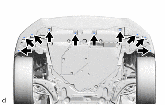
| (a) Remove the 10 screws. |
|
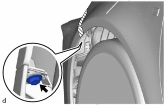
| (b) Remove the screw. HINT: Use the same procedure for the RH side and LH side. |
|
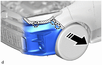
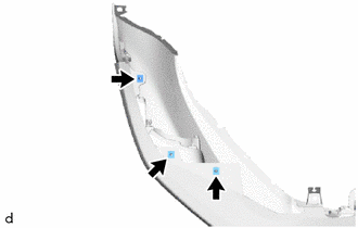
(c) Disengage the claws to remove the bracket as shown in the illustration.
.png) | Remove in this Direction |
HINT:
Use the same procedure for the RH side and LH side.
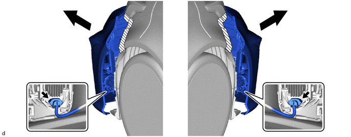
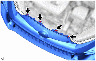
(d) Disengage the claws to separate the front bumper assembly as shown in the illustration.
HINT:
Use the same procedure for the RH side and LH side.
|
| Separate in this Direction |
(e) Pull back the side of the front bumper assembly.
NOTICE:
Do not apply excessive force when pulling back the front bumper assembly.
(f) Disconnect the 2 connectors.
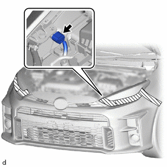
(g) w/ Pre-collision System:
| (1) Disconnect the connector. |
|
| (h) Remove the 2 clips, 2 bolts and front bumper assembly. |
|
| (i) Remove the 3 grommets. HINT: Use the same procedure for the RH side and LH side. |
|
 Components
COMPONENTS ILLUSTRATION
*1 FRONT BUMPER ASSEMBLY *2 PIN HOLD CLIP ILLUSTRATION
*A w/ Pre-collision System - - *1 NO. 3 ENGINE ROOM WIRE *2 MILLIMETER WAVE RADAR SENSOR ASSEMBLY
N*m (kgf*cm, ft...
 Disassembly
DISASSEMBLY PROCEDURE 1. REMOVE MILLIMETER WAVE RADAR SENSOR ASSEMBLY (w/ Pre-collision System) Click here
2. REMOVE NO. 3 ENGINE ROOM WIRE (w/ Pre-collision System) (a) Disengage the clamps to remove the No...
Other information:
Toyota Yaris XP210 (2020-2026) Owner's Manual: Windshield Wipers and Washer
The ignition must be switched ON to use the wipers. Because heavy ice and snow can jam the wiper blades, the wiper motor is protected from motor breakdown, overheating and possible fire by a circuit breaker. This mechanism will automatically stop operation of the blades, but only for about 5 minutes...
Toyota Yaris XP210 (2020-2026) Reapir and Service Manual: Starter Exceed Limited Number (P154563)
DESCRIPTION When the number of starter operations reaches the maximum number, the engine stop and start ECU stores DTC P154563 and blinks the stop and start cancel indicator. DTC No. Detection Item DTC Detection Condition Trouble Area Warning Indicate Memory Note P154563 Starter Exceed Limited Number Both of the following conditions are met (1 trip detection logic): Ignition switch ON...
Categories
- Manuals Home
- Toyota Yaris Owners Manual
- Toyota Yaris Service Manual
- Maintenance
- Fuse Panel Description
- Power Integration No.1 System Missing Message (B235287,B235587,B235787-B235987)
- New on site
- Most important about car
Liftgate/Trunk Lid
WARNING
Never allow a person to ride in the luggage compartment/trunk
Allowing a person to ride in the luggage compartment/trunk is dangerous. The person in the luggage compartment/trunk could be seriously injured or killed during sudden braking or a collision.
Do not drive with the liftgate/trunk lid open