Toyota Yaris: Backup Boost Converter / Removal
REMOVAL
CAUTION / NOTICE / HINT
NOTICE:
After the ignition switch is turned off, the radio and display receiver assembly records various types of memory and settings. As a result, after turning the ignition switch off, make sure to wait at least 120 seconds before disconnecting the cable from the negative (-) auxiliary battery terminal.
HINT:
When the cable is disconnected/reconnected to the auxiliary battery terminal, systems temporarily stop operating. However, each system has a function that completes learning the first time the system is used.
-
Learning completes when vehicle is driven
Effect/Inoperative Function When Necessary Procedures are not Performed
Necessary Procedures
Link
Lane tracing assist system
Drive the vehicle straight ahead at 35 km/h (22 mph) or more for 5 second or more.

Pre-collision system
Stop and start system
Drive the vehicle until stop and start control is permitted (approximately 5 to 60 minutes)

-
Learning completes when vehicle is operated normally
Effect/Inoperative Function When Necessary Procedures are not Performed
Necessary Procedures
Link
Power door lock control system
- Back door opener
Perform door unlock operation with door control switch or electrical key transmitter sub-assembly switch.

Air conditioning system
After the ignition switch is turned to ON, the servo motor standard position is recognized.
-
PROCEDURE
1. PRECAUTION
NOTICE:
After turning the ignition switch off, waiting time may be required before disconnecting the cable from the negative (-) auxiliary battery terminal.
Click here

2. DISCONNECT CABLE FROM NEGATIVE AUXILIARY BATTERY TERMINAL
Click here

3. REMOVE FRONT BUMPER ASSEMBLY
Click here

4. REMOVE ECO RUN VEHICLE CONVERTER ASSEMBLY
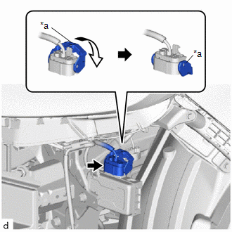
| (a) Move the lock lever as shown in the illustration and disconnect the eco run vehicle converter assembly connector. |
|
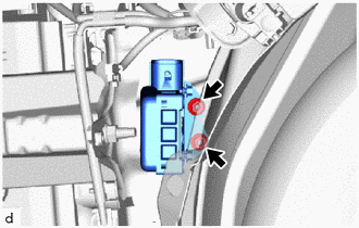
| (b) Remove the bolt, nut and eco run vehicle converter assembly. |
|
5. REMOVE NO. 1 CONVERTER CONTROL BRACKET
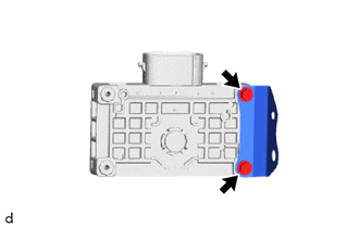
| (a) Remove the 2 bolts and No. 1 converter control bracket from the eco run vehicle converter assembly. |
|
 Installation
INSTALLATION PROCEDURE 1. INSTALL NO. 1 CONVERTER CONTROL BRACKET (a) Install the No. 1 converter control bracket to the eco run vehicle converter assembly with the 2 bolts...

Other information:
Toyota Yaris XP210 (2020-2026) Reapir and Service Manual: Components
C..
Toyota Yaris XP210 (2020-2026) Reapir and Service Manual: Installation
INSTALLATION CAUTION / NOTICE / HINT NOTICE: When the manual transaxle assembly is removed, be sure to use a new clutch release cylinder with bearing assembly and new installation bolts. Removal of the manual transaxle assembly allows the compressed clutch release cylinder with bearing assembly to return to its original position...
Categories
- Manuals Home
- Toyota Yaris Owners Manual
- Toyota Yaris Service Manual
- Battery Monitor Module General Electrical Failure (P058A01)
- Key Battery Replacement
- How to use USB mode
- New on site
- Most important about car
Fuel Gauge
The fuel gauge shows approximately how much fuel is remaining in the tank when the ignition is switched ON. We recommend keeping the tank over 1/4 full.
