Toyota Yaris: Engine Unit / Removal
REMOVAL
CAUTION / NOTICE / HINT
The necessary procedures (adjustment, calibration, initialization, or registration) that must be performed after parts are removed and installed, or replaced during engine unit removal/installation are shown below.
Necessary Procedure After Parts Removed/Installed/Replaced| Replaced Part or Performed Procedure | Necessary Procedure | Effect/Inoperative Function when Necessary Procedure not Performed | Link |
|---|---|---|---|
| Inspection after repair |
|
|

PROCEDURE
1. REMOVE COMPRESSOR WITH PULLEY ASSEMBLY
Click here

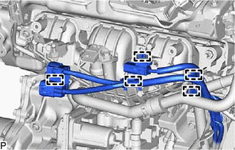
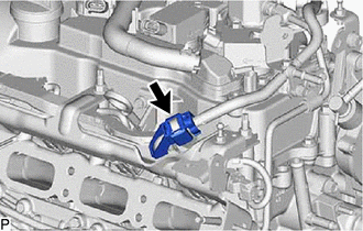
2. REMOVE FUEL TUBE SUB-ASSEMBLY
| (a) Disengage the clamp. |
|
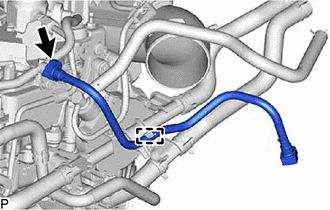
(b) Remove the fuel tube sub-assembly from the fuel pipe sub-assembly.
Click here

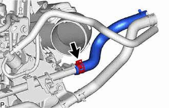
3. REMOVE HEATER WATER HOSE INLET
| (a) Slide the clip and remove the heater water hose inlet from the No. 1 water by-pass pipe. |
|
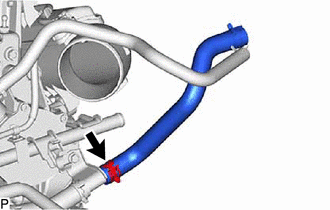
4. REMOVE HEATER WATER HOSE OUTLET
| (a) Slide the clip and remove the heater water hose outlet from the No. 3 water by-pass pipe. |
|
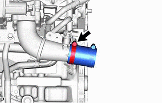
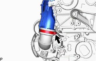
5. REMOVE NO. 2 AIR HOSE
| (a) Loosen the hose clamp and remove the No. 2 air hose from the turbocharger sub-assembly. |
|
6. REMOVE NO. 5 AIR HOSE
| (a) Loosen the hose clamp and remove the No. 5 air hose from the air tube assembly. |
|
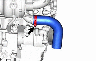
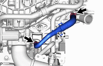
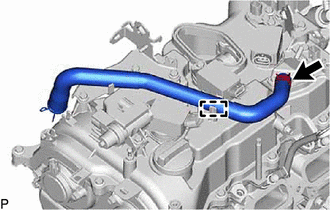
7. REMOVE NO. 6 WATER BY-PASS HOSE
| (a) Slide the 2 clips and separate the No. 6 water by-pass hose. |
|
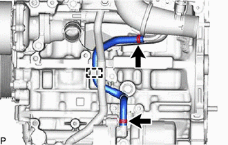
(b) Disengage the clamp and remove the No. 6 water by-pass hose from the No. 1 water hose clamp bracket.
8. REMOVE NO. 5 WATER BY-PASS HOSE
| (a) Slide the 2 clips and separate the No. 5 water by-pass hose. |
|
(b) Remove the bolt and No. 5 water by-pass hose from the crankshaft bearing cap assembly.
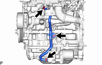
9. REMOVE NO. 3 VACUUM TRANSMITTING HOSE
| (a) Disengage the 2 clamp and remove the No. 3 vacuum transmitting hose. |
|
10. REMOVE UNION TO CONNECTOR TUBE HOSE
Click here

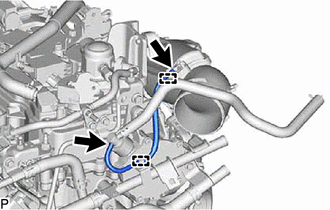
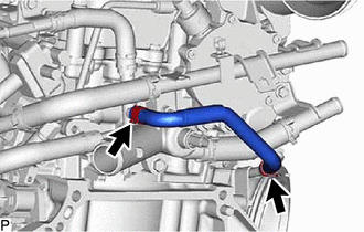
11. REMOVE NO. 1 TURBO WATER HOSE
| (a) Slide the 2 clips and remove the No. 1 turbo water hose. |
|
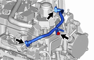
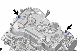
12. REMOVE NO. 1 WATER BY-PASS PIPE
| (a) Slide the clip and separate the water by-pass hose. |
|
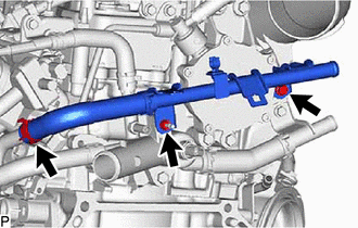
(b) Remove the bolt, nut and No. 1 water by-pass pipe.
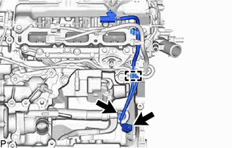
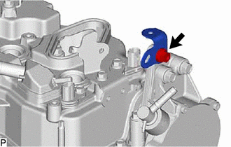
13. REMOVE NO. 3 WATER BY-PASS PIPE
| (a) Remove the bolt and separate the No. 3 water by-pass pipe. |
|
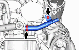
(b) Slide the clip and remove the No. 3 water by-pass pipe.
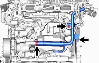
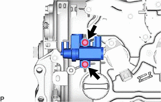
14. REMOVE NO. 4 WATER BY-PASS PIPE
| (a) Remove the 3 bolts and separate the No. 4 water by-pass pipe. |
|
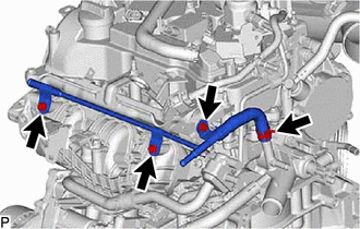
(b) Slide the clip and remove the No. 4 water by-pass pipe.
15. REMOVE WATER BY-PASS HOSE ASSEMBLY
| (a) Disengage the clamp. |
|
(b) Slide the 2 clips and remove the water by-pass hose assembly.
16. REMOVE E.F.I. VACUUM SENSOR ASSEMBLY
Click here

17. REMOVE INTAKE AIR PIPE
| (a) Separate the No.1 vaccum transmitting hose. |
|
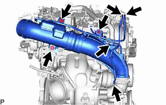
(b) Separate the No. 2 vaccum transmitting hose.
(c) Separate the ventilation hose.
(d) Remove the e3 bolts.
| (e) Loosen the hose clamp and remove the intake air pipe from the . |
|
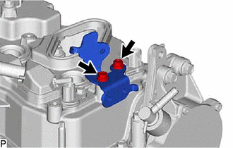
18. REMOVE ENGINE HANGER BRACKET
| (a) Remove the 2 bolts and engine hanger bracket from the cylinder head sub-assembly. |
|
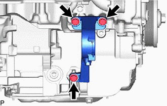
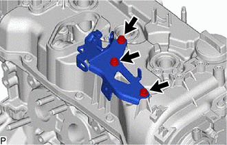
19. REMOVE DRIVE SHAFT BEARING BRACKET
| (a) Remove the 3 bolts and drive shaft bearing bracket from the cylinder block sub-aseembly. |
|
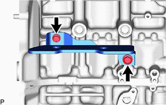
20. REMOVE NO. 4 CYLINDER BROCK INSULATOR
| (a) Remove the 2 bolts and No. 4 cylinder brock insulator. |
|
21. REMOVE NO. 1 TURBO INSULATOR
Click here

22. REMOVE TURBOCHARGER SUB-ASSEMBLY
| (a) Remove the 2 bolts and separate the outlet turbo oil pipe. |
|
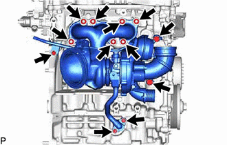
(b) Remove the inlet turbo oil pipe union bolt.
(c) Remove the 2 bolts and separate the No. 1 turbo water pipe sub-assembly.
(d) Remove the 7 nuts and turbocharger sub-aseembly from the cylinder head sub-aseembly.
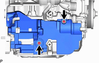
23. REMOVE NO. 2 TURBO INSULATOR
| (a) Remove the 2 bolts and No. 2 turbo insulator from the cylinder brock sub-assembly. |
|
24. REMOVE PURGE VALVE (PURGE VSV)
Click here

25. REMOVE NO. 6 ENGINE WIRE
| (a) Disengage the 5 clamps and separate the No. 6 engine wire. |
|
26. REMOVE NO. 2 ENGINE COVER BRACKET
| (a) Remove the bolt and No. 2 engine cover bracket from the intake manifold. |
|
27. REMOVE INTAKE AIR CONNECTOR BRACKET
Click here

28. REMOVE INTAKE MANIFOLD
Click here

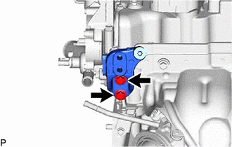
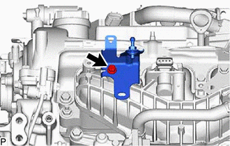
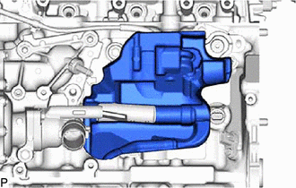
29. REMOVE WATER BY-PASS PIPE
| (a) Remove the bolt and nut. |
|
(b) Slide the clip and remove the water by-pass pipe from the water inlet with thermostat sub-assembly.
30. REMOVE NO. 7 ENGINE WIRE
| (a) Disengage the clamp. |
|
(b) Disconnect the 2 connectors and remove the No. 7 engine wire.
31. REMOVE FUEL TUBE SUB-ASSEMBLY
| (a) Remove the fuel pipe clamp from the fuel tube connector. |
|
| (b) Remove the bolt. |
|
(c) Remove the fuel tube sub-assembly.
Click here

32. REMOVE OIL LEVEL GAUGE SUB-ASSEMBLY
Click here

33. REMOVE OIL LEVEL GAUGE GUIDE
Click here

34. REMOVE FUEL DELIVERY GUARD
Click here

35. REMOVE NO. 1 DELIVERY PIPE SPACER
(a) Remove the No. 1 delivery pipe spacer.
36. REMOVE FUEL DELIVERY PIPE (for Low Pressure)
Click here

37. REMOVE FUEL DELIVERY SPACER
Click here

38. REMOVE INJECTOR VIBRATION INSULATOR
Click here

39. REMOVE NO. 1 FUEL PIPE SUB-ASSEMBLY
Click here

40. REMOVE FUEL PUMP ASSEMBLY (ENGINE ROOM SIDE)
Click here

41. REMOVE NO. 1 VENTILATION FLANGE SEPARATOR
Click here

42. REMOVE FUEL DELIVERY PIPE SUB-ASSEMBLY (for High Pressure)
Click here

43. REMOVE NO. 6 ENGINE WIRE
Click here

44. REMOVE DIRECT FUEL INJECTOR ASSEMBLY
Click here

45. REMOVE FUEL INJECTOR SEAL
Click here

46. REMOVE NO. 2 CYLINDER BLOCK INSULATOR
| (a) Remove the No. 2 cylinder block insulator from the cylinder block sub-assembly. |
|
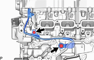
47. REMOVE SENSOR WIRE
| (a) Remove the 2 bolts and remove the sensor wire from the cylinder block sub-assembly. |
|
48. REMOVE VENTILATION HOSE
| (a) Disengage the clamp. |
|
(b) Slide the clip and remove the ventilation hose from the cylinder head cover sub-assembly.
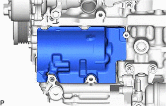
49. REMOVE VACUUM REGULATING VALVE ASSEMBLY
| (a) Remove the 2 bolts and vacuum regulating valve assembly from the cylinder head cover sub-assembly. |
|
50. REMOVE IGNITION COIL ASSEMBLY
Click here

51. REMOVE ENGINE COVER JOINT
| (a) Remove the 2 engine cover joints from the cylinder head cover sub-assembly. |
|
52. REMOVE ENGINE COVER BRACKET
| (a) Remove the bolt and engine cover bracket from the No. 1 vacuum pump bracket. |
|
53. REMOVE FUEL HOSE BRACKET
| (a) Remove the 2 bolts and fuel hose bracket form the cylinder head cover sub-assembly. |
|
54. REMOVE INTAKE PIPE OR HOSE STAY
| (a) Remove the 3 bolts and intake pipe or hose stay from the cylinder head cover sub-assembly. |
|
55. REMOVE NO. 3 CYLINDER BLOCK INSULATOR
| (a) Remove the No. 3 cylinder block insulator from the cylinder block sub-assembly. |
|
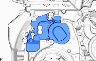
56. REMOVE TIMING GEAR COVER INSULATOR
| (a) Remove the timing gear cover insulator from the timing chain cover assembly. |
|
 Components
COMPONENTS ILLUSTRATION
*1 FUEL TUBE SUB-ASSEMBLY *2 HEATER WATER HOSE INLET *3 HEATER WATER HOSE OUTLET *4 NO. 2 AIR HOSE *5 NO...
 Disassembly
DISASSEMBLY CAUTION / NOTICE / HINT NOTICE: This procedure includes the installation of small-head bolts. Refer to Small-Head Bolts of Basic Repair Hint to identify the small-head bolts...
Other information:
Toyota Yaris XP210 (2020-2026) Owner's Manual: Driving on Uneven Road
Your vehicle’s suspension and underbody can be damaged if driven on rough/uneven roads or over speed bumps at excessive speeds. Use care and reduce speed when traveling on rough/uneven roads or over speed bumps. Use care not to damage the vehicle’s underbody, bumpers or muffler(s) when driving under the following conditions: Ascending or descending a slope with a sharp transition angle Ascending or descending a driveway or trailer ramp with a sharp transition angle NOTICE This vehicle is equipped with low profile tires allowing class-leading performance and handling...
Toyota Yaris XP210 (2020-2026) Owner's Manual: Bluetooth® Preparation
Device pairing To use Bluetooth® audio and Hands-Free, the device equipped with Bluetooth® has to be paired to the unit using the following procedure. A maximum of 7 devices including Bluetooth® audio devices and hands-free mobile phones can be paired...
Categories
- Manuals Home
- Toyota Yaris Owners Manual
- Toyota Yaris Service Manual
- Maintenance
- Key Battery Replacement
- Headlights
- New on site
- Most important about car
Key Suspend Function
If a key is left in the vehicle, the functions of the key left in the vehicle are temporarily suspended to prevent theft of the vehicle.
To restore the functions, press the unlock button on the functions-suspended key in the vehicle.