Toyota Yaris: Engine Unit / Disassembly
DISASSEMBLY
CAUTION / NOTICE / HINT
NOTICE:
This procedure includes the installation of small-head bolts. Refer to Small-Head Bolts of Basic Repair Hint to identify the small-head bolts.
Click here

PROCEDURE
1. REMOVE SPARK PLUG
Click here

2. REMOVE OIL PRESSURE AND TEMPERATURE SENSOR
Click here

3. REMOVE CAMSHAFT POSITION SENSOR (for Intake Side)
Click here

4. REMOVE CAMSHAFT POSITION SENSOR (for Exhaust Side)
Click here

5. REMOVE CAMSHAFT TIMING OIL CONTROL SOLENOID ASSEMBLY (for Intake Side)
Click here

6. REMOVE AND INSTALL CAMSHAFT TIMING OIL CONTROL SOLENOID ASSEMBLY (for Exhaust Side)
Click here

7. REMOVE AND INSTALL WATER INLET WITH THERMOSTAT SUB-ASSEMBLY
Click here

8. REMOVE WATER INLET WITH WATER PUMP HOUSING SUB-ASSEMBLY
Click here

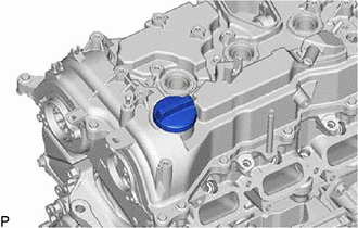
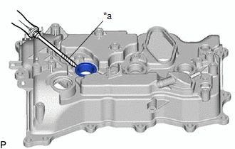
9. REMOVE OIL FILLER CAP ASSEMBLY
| (a) Remove the oil filler cap sub-assembly from the cylinder head cover sub-assembly. |
|
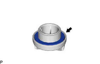
10. REMOVE OIL FILLER CAP GASKET
| (a) Remove the oil filler cap gasket from the oil filler cap sub-assembly. |
|
11. REMOVE CRANKSHAFT POSITION SENSOR
Click here

12. REMOVE PCV VALVE (VENTILATION VALVE SUB-ASSEMBLY)
Click here

13. REMOVE VACUUM PUMP ASSEMBLY
Click here

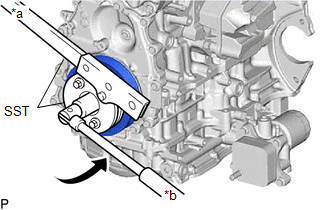
14. REMOVE CRANKSHAFT PULLEY ASSEMBLY
| (a) Using SST, hold the crankshaft pulley assembly and loosen the crankshaft pulley set bolt. Further loosen the crankshaft pulley set bolt until 2 or 3 threads remain screwed into the crankshaft. SST: 09213-54015 SST: 09330-00021 |
|
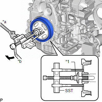
| (b) Using SST and the crankshaft pulley set bolt, remove the crankshaft pulley assembly and crankshaft pulley set bolt. SST: 09950-50013 09951-05010 09952-05010 09953-05020 09954-05070 09957-04010 HINT: Apply lubricant to the threads and end of SST. |
|
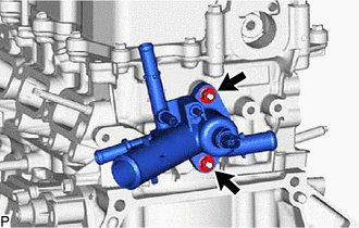
15. REMOVE OUTLET WATER SUB-ASSEMBLY
| (a) Remove the 2 nuts, outlet water sub-aseembly and water outlet gasket from the cylinder head sub-assembly. |
|
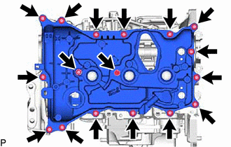
16. REMOVE CYLINDER HEAD COVER SUB-ASSEMBLY
| (a) Remove the 17 bolts and cylinder head cover sub-assembly from the cylinder head sub-assembly. |
|
| (b) Remove the 5 cylinder head cover gaskets from the cylinder head cover sub-assembly. |
|
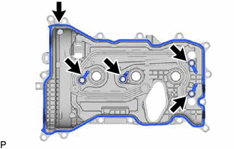
| (c) Remove the 2 camshaft bearing cap oil hole gaskets from the No. 1 camshaft bearing cap and fuel pump lifter housing. |
|
17. REMOVE SPARK PLUG TUBE GASKET
| (a) Using a screwdriver, pry out the 3 spark plug tube gaskets from the cylinder head cover sub-assembly. NOTICE: Be careful not to damage the cylinder head cover sub-assembly. HINT: Tape the screwdriver tip before use. |
|
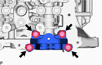
18. REMOVE NO. 1 VACUUM PUMP BRACKET
| (a) Remove the 4 bolts and No. 1 vacuum pump bracket from the cylinder head sub-assembly. |
|
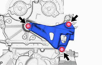
19. REMOVE ENGINE MOUNTING BRACKET RH
| (a) Remove the 3 bolts and engine mounting bracket RH from the No. 2 timing chain cover assembly. |
|
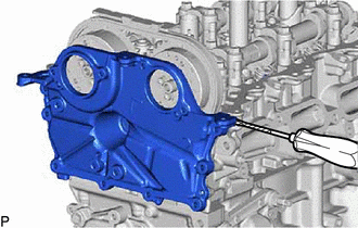
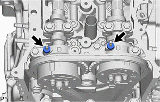
20. REMOVE NO. 2 TIMING CHAIN COVER ASSEMBLY
| (a) Remove the 8 bolts. |
|
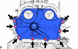
| (b) Remove the No. 2 timing chain cover assembly from the cylinder head sub-assembly by prying the No. 2 timing chain cover assembly with a screwdriver with its tip wrapped with protective tape. |
|
21. REMOVE TIMING CHAIN COVER OIL SEAL
Click here

22. REMOVE TIMING CHAIN COVER ASSEMBLY
Click here

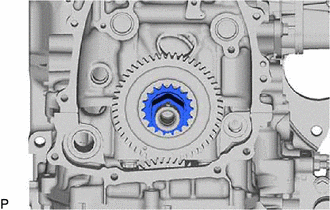
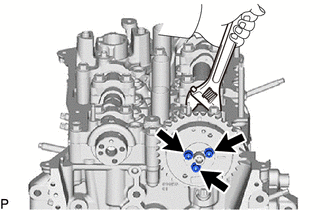
23. SET NO. 1 CYLINDER TO TDC (COMPRESSION)
(a) Temporarily install the crankshaft pulley bolt.
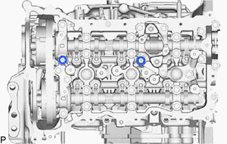
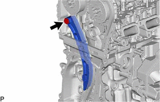
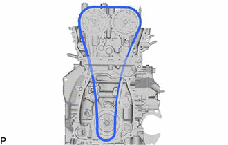
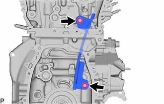
| (b) Rotate the crankshaft clockwise and make sure that the timing mark of the camshaft timing gear assembly and camshaft timing exhaust gear assembly is at the top. |
|
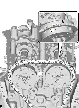
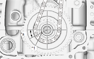
| (c) Check that the crankshaft timing gear key as shown in the illustration. |
|
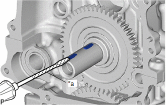
(d) Remove the crankshaft pulley bolt.
HINT:
As the exhaust camshaft sub-assembly may rotate counterclockwise strongly when the crankshaft pulley bolt is removed, use a wrench to hold the hexagonal portion of the exhaust camshaft sub-assembly.
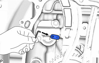
24. REMOVE NO. 1 CHAIN TENSIONER ASSEMBLY
| (a) Turn the stopper plate of the No. 1 chain tensioner assembly clockwise to release the lock and push in the plunger. |
|
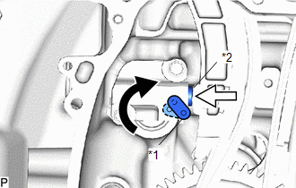
(b) Turn the stopper plate counterclockwise to set the lock.
| (c) Turn the stopper plate clockwise to set the lock, and insert a pin into the stopper plate hole. |
|
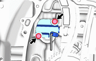
| (d) Remove the 2 bolts and No. 1 chain tensioner assembly from the cylinder block sub-assembly. |
|
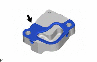
| (e) Remove the chain tensioner gasket from the No. 1 chain tensioner assembly. |
|
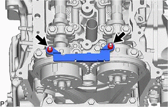
25. REMOVE TIMING CHAIN GUIDE
| (a) Remove the 2 nut and timing chain guide from the damper plate spacer. |
|
26. REMOVE DAMPER PLATE SPACER
| (a) Remove the damper plate spacer from the No. 1 camshaft bearing cap. |
|
27. REMOVE CHAIN TENSIONER SLIPPER
| (a) Remove the bolt and chain tensioner slipper from the cylinder head sub-assembly. |
|
28. REMOVE CHAIN SUB-ASSEMBLY
| (a) Remove the chain sub-assembly. |
|
29. REMOVE NO. 1 CHAIN VIBRATION DAMPER
| (a) Remove the 2 bolts and No. 1 chain vibration damper from the timing chain cover assembly. |
|
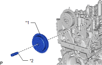
30. REMOVE CRANKSHAFT TIMING GEAR OR SPROCKET
| (a) Remvoe the crankshaft timing gear or sprocket from the crankshaft. |
|
31. REMOVE CRANKSHAFT TIMING GEAR KEY
| (a) Using a screwdriver, remove the 2 crankshaft timing gear keys from the crankshaft. HINT: Tape the screwdriver tip before use. |
|
32. REMOVE CAMSHAFT TIMING EXHAUST GEAR ASSEMBLY
| (a) Using a wrench, hold the hexagonal portion of the exhaust camshaft sub-assembly. NOTICE: Be careful not to damage the camshaft housing sub-assembly, cylinder head sub-assembly or spark plug tube with the wrench. |
|
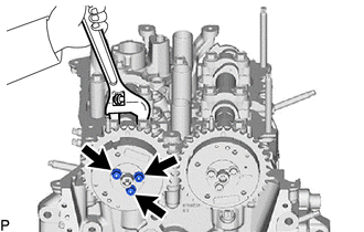
(b) Using a 5 mm hexagon socket wrench, remove the 3 bolts.
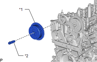
| (c) Remove the camshaft timing exhaust gear assembly and camshaft timing oil control valve assembly (exhaust camshaft timing gear bolt assembly) from the exhaust camshaft sub-assembly. |
|
33. REMOVE CAMSHAFT TIMING GEAR ASSEMBLY
| (a) Using a wrench, hold the hexagonal portion of the intake camshaft sub-assembly. NOTICE: Be careful not to damage the cylinder head sub-assembly or spark plug tube with the wrench. |
|
(b) Using a 5 mm hexagon socket wrench, remove the 3 bolts.
| (c) Remove the camshaft timing gear assembly and camshaft timing oil control valve assembly (camshaft timing gear bolt assembly) from the intake camshaft sub-assembly. |
|
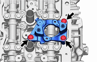
34. REMOVE FUEL PUMP LIFTER GUIDE
| (a) Remove the 2 bolts and fuel pump lifter guide from the fuel pump lifter housing. |
|
35. REMOVE FUEL PUMP LIFTER HOUSING
| (a) Remove the 3 bolts and fuel pump lifter housing from the cylinder head sub-aseembly. |
|
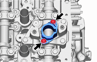
36. REMOVE CAMSHAFT POSITION SENSOR HOLDER
| (a) Remove the bolt and camshaft position sensor holder from the cylinder head sub-assembly. |
|
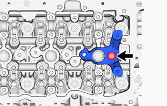
37. REMOVE CAMSHAFT BEARING CAP
| (a) Remove the 16 bolts. |
|
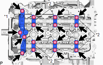
(b) Remove the No. 2 camshaft bearing cap, 6 No. 4 camshaft bearing caps from the No. 1 camshaft bearing cap and No. 3 camshaft bearing cap.
HINT:
Arrange the removed parts in such a way that they can be reinstalled to their original locations.
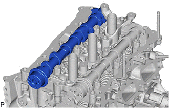
38. REMOVE EXHAUST CAMSHAFT SUB-ASSEMBLY
| (a) Remove the exhaust camshaft sub-assembly from the camshaft housing sub-assembly. |
|
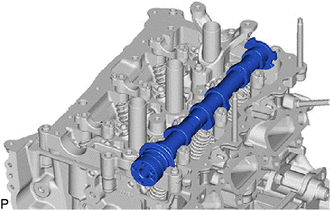
39. REMOVE INTAKE CAMSHAFT SUB-ASSEMBLY
| (a) Remove the intake camshaft sub-assembly from the camshaft housing sub-assembly. |
|
40. REMOVE NO. 1 CAMSHAFT BEARING CAP
| (a) Remove the No. 1 camshaft bearing cap from the cylinder head sub-assembly. |
|
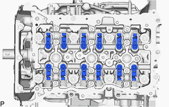
41. REMOVE NO. 1 VALVE ROCKER ARM SUB-ASSEMBLY
| (a) Remove the 12 No. 1 valve rocker arm sub-assemblies from the cylinder head sub-assembly. HINT: Arrange the removed parts in such a way that they can be reinstalled to their original locations. |
|
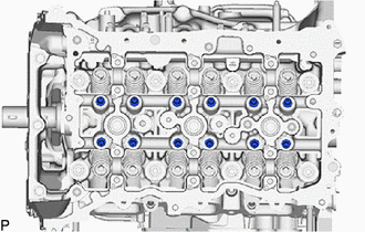
42. REMOVE VALVE LASH ADJUSTER ASSEMBLY
| (a) Remove the 12 valve lash adjuster assemblies from the cylinder head sub-assembly. HINT: Arrange the removed parts in such a way that they can be reinstalled to their original locations. |
|
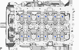
43. REMOVE VALVE STEM CAP
| (a) Remove the 12 valve stem caps from the cylinder head sub-assembly. HINT: Arrange the removed parts in such a way that they can be reinstalled to their original locations. |
|
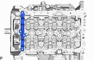
44. REMOVE CYLINDER HEAD SUB-ASSEMBLY
| (a) Using a 12 mm socket wrench, uniformly loosen the 8 cylinder head set bolts in the order shown in the illustration. Remove the 8 cylinder head set bolts and 8 plate washers. NOTICE:
HINT: Arrange the removed parts in such a way that they can be reinstalled to their original locations. |
|
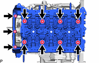
(b) Remove the 3 bolts and cylinder head sub-assembly from the cylinder block sub-assembly.
45. REMOVE CYLINDER HEAD GASKET
Click here

46. REMOVE OIL FILTER SUB-ASSEMBLY
Click here

47. REMOVE OIL FILTER UNION
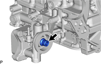
(a) Using a 12 mm hexagon socket wrench, remove the oil filter union from the stiffening crankcase assembly.
48. REMOVE OIL COOLER ASSEMBLY
Click here

49. REMOVE OIL FILTER BRACKET SUB-ASSEMBLY
| (a) Remvoe the 3 bolts and oil filter bracket sub-assembly from the cylinder block sub-aseembly. |
|
| (b) Remove the 2 gaskets. |
|
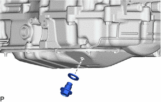
50. REMOVE OIL PAN DRAIN PLUG
| (a) Remove the oil pan drain plug and gasket from the No. 2 oil pan sub-assembly. |
|
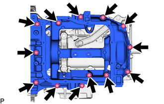
51. REMOVE NO. 2 OIL PAN SUB-ASSEMBLY
| (a) Remove the 10 bolts and 2 nuts. |
|
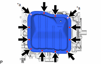
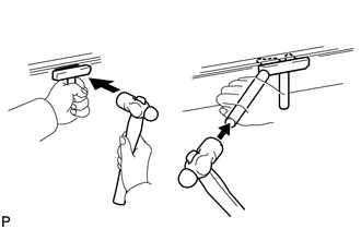
| (b) Insert the blade of an oil pan seal cutter between the oil pan sub-assembly and stiffening crankcase assembly, cut through the applied sealer and remove the oil pan sub-assembly. NOTICE:
|
|
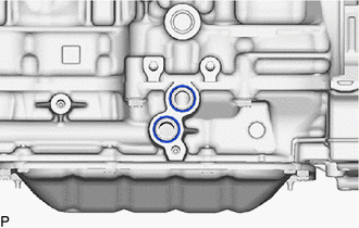
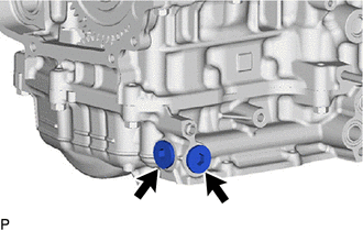
52. REMOVE NO. 1 OIL PAN PLUG
| (a) Using a 10 mm hexagon socket wrench, remove the 2 No. 1 oil pan plugs and 2 gaskets from the oil pan sub-assembly. |
|
53. REMOVE OIL PAN SUB-ASSEMBLY
| (a) Remove the 13 bolts and oil pan sub-aseembly from the crankshaft bearing cap assembly. |
|
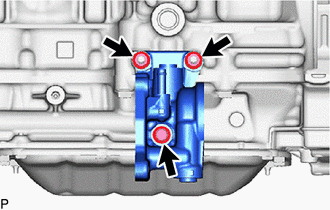
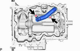
54. REMOVE OIL STRAINER SUB-ASSEMBLY
| (a) Remove the 2 bolts, oil strainer sub-assembly and oil strainer gasket from the cylinder block sub-assembly. |
|
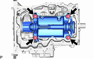
55. REMOVE ENGINE BALANCER ASSEMBLY
| (a) Remove the 4 bolts and engine balancer assembly from the cylinder block sub-assembly. |
|
56. REMOVE BALANCESHAFT HOUSING SPACER
| (a) Remove the balanceshaft housing spacer from the cylinder block sub-assembly. |
|
57. REMOVE REAR ENGINE OIL SEAL
Click here

58. REMOVE STUD BOLT
NOTICE:
If a stud bolt is deformed or its threads are damaged, replace it.
59. REMOVE RING PIN
NOTICE:
It is not necessary to remove the ring pins unless they are being replaced.
 Removal
REMOVAL CAUTION / NOTICE / HINT The necessary procedures (adjustment, calibration, initialization, or registration) that must be performed after parts are removed and installed, or replaced during engine unit removal/installation are shown below...
 Inspection
INSPECTION PROCEDURE 1. INSPECT NO. 1 VALVE ROCKER ARM SUB-ASSEMBLY (a) Turn the roller by hand to check that it turns smoothly. HINT: If the roller does not turn smoothly, replace the No...
Other information:
Toyota Yaris XP210 (2020-2026) Reapir and Service Manual: Dtc Check / Clear
DTC CHECK / CLEAR HINT: DTCs, which are stored in the engine stop and start ECU, can be displayed on the GTS. The GTS can display confirmed and pending DTCs. Some DTCs are not stored if the engine stop and start ECU does not detect the same malfunction again during a second consecutive driving cycle...
Toyota Yaris XP210 (2020-2026) Reapir and Service Manual: System Description
SYSTEM DESCRIPTION POWER MIRROR CONTROL SYSTEM DESCRIPTION (a) This system has the following functions: electrical remote control mirror function, power retract mirror function, auto power retract mirror function and mirror heater function. FUNCTION OF MAIN COMPONENT Component Function Outer rear view mirror assembly Vertical mirror motor Receives signals from the outer mirror switch assembly and adjusts the mirror surface position vertically...
Categories
- Manuals Home
- Toyota Yaris Owners Manual
- Toyota Yaris Service Manual
- Fuse Panel Description
- How to connect USB port/Auxiliary jack
- Power Integration No.1 System Missing Message (B235287,B235587,B235787-B235987)
- New on site
- Most important about car
Fuel-Filler Lid and Cap
WARNING
When removing the fuel-filler cap, loosen the cap slightly and wait for any hissing to stop, then remove it
Fuel spray is dangerous. Fuel can burn skin and eyes and cause illness if ingested. Fuel spray is released when there is pressure in the fuel tank and the fuel-filler cap is removed too quickly.