Toyota Yaris: Engine Unit / Inspection
INSPECTION
PROCEDURE
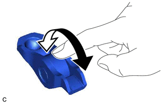
1. INSPECT NO. 1 VALVE ROCKER ARM SUB-ASSEMBLY
| (a) Turn the roller by hand to check that it turns smoothly. HINT: If the roller does not turn smoothly, replace the No. 1 valve rocker arm sub-assembly. |
|
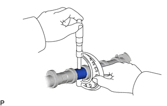
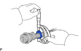
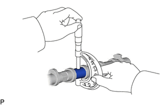
2. INSPECT VALVE LASH ADJUSTER ASSEMBLY
NOTICE:
- Keep the valve lash adjuster assembly free from dirt and foreign matter.
- Only use clean engine oil.
(a) Place the valve lash adjuster assembly into a container filled with engine oil.
(b) Insert the tip of SST into the valve lash adjuster assembly plunger and use the tip to press down on the check ball inside the plunger.
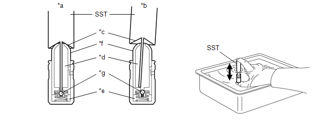
| *a | Correct | *b | Incorrect |
| *c | Tapered Path | *d | Low Pressure Chamber |
| *e | High Pressure Chamber | *f | Plunger |
| *g | Check Ball | - | - |
SST: 09276-75010
(c) Squeeze SST and the valve lash adjuster assembly together to move the plunger up and down 5 to 6 times.
(d) Check the movement of the plunger and bleed the air.
OK:
Plunger moves up and down.
NOTICE:
When bleeding air from the high-pressure chamber, make sure that the tip of SST is pressing the check ball as shown in the illustration. If the check ball is not pressed, air will not bleed.
(e) After bleeding the air, remove SST. Then try to quickly and firmly press the plunger by hand.
OK:
The plunger is very difficult to move.
HINT:
If the plunger is easy to move, replace the valve lash adjuster assembly.
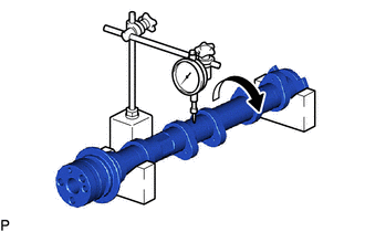
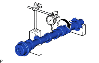
3. INSPECT INTAKE CAMSHAFT SUB-ASSEMBLY
| (a) Inspect the intake camshaft sub-assembly for runout. (1) Place the intake camshaft sub-assembly on V-blocks. (2) Using a dial indicator, measure the runout at the center journal. Maximum Runout: 0.03 mm (0.00118 in.) HINT:
|
|
| (b) Inspect the cam lobes. (1) Using a micrometer, measure the cam lobe height. Standard Cam Lobe Height: 38.303 to 38.403 mm (1.508 to 1.512 in.) Minimum Cam Lobe Height: 38.302 mm (1.5079 in.) HINT: If the cam lobe height is less than the minimum, replace the intake camshaft sub-assembly. |
|
| (c) Inspect the intake camshaft sub-assembly journals. (1) Using a micrometer, measure the journal diameter. Standard Journal Diameter:
|
|
4. INSPECT EXHAUST CAMSHAFT SUB-ASSEMBLY
| (a) Inspect the exhaust camshaft sub-assembly for runout. (1) Place the exhaust camshaft sub-assembly on V-blocks. (2) Using a dial indicator, measure the runout at the center journal. Maximum Runout: 0.03 mm (0.00118 in.) HINT:
|
|
| (b) Inspect the cam lobes. (1) Using a micrometer, measure the cam lobe height. Standard Cam Lobe Height:
Minimum Cam Lobe Height:
HINT: If the cam lobe height is less than the minimum, replace the exhaust camshaft sub-assembly. |
|
| (c) Inspect the exhaust camshaft sub-assembly journals. (1) Using a micrometer, measure the journal diameter. Standard Journal Diameter:
|
|
5. INSPECT CHAIN SUB-ASSEMBLY
| (a) Using a spring scale, pull the chain sub-assembly with a force of 147 N (15 kgf, 33.0 lbf) as shown in the illustration. |
|
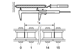
(b) Using a vernier caliper, measure the length of 15 links.
Maximum Chain Elongation:
116.30 mm (4.58 in.)
NOTICE:
Perform the measurement at 3 random places. Use the average of the measurements.
HINT:
If the average elongation is more than the maximum, replace the chain sub-assembly.
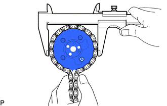
6. INSPECT CAMSHAFT TIMING GEAR ASSEMBLY

(a) Place the chain sub-assembly around the camshaft timing gear assembly.
(b) Using a vernier caliper, measure the diameter of the camshaft timing gear assembly and chain sub-assembly.
Minimum Gear Diameter (with Chain Sub-assembly):
114.09 mm (4.49 in.)
NOTICE:
The vernier caliper must be in contact with the chain rollers when measuring.
HINT:
If the diameter is less than the minimum, replace the chain sub-assembly and camshaft timing gear assembly.
7. INSPECT CAMSHAFT TIMING EXHAUST GEAR ASSEMBLY
(a) Place the chain sub-assembly around the camshaft timing exhaust gear assembly.
(b) Using a vernier caliper, measure the diameter of the camshaft timing exhaust gear assembly and chain sub-assembly.
Minimum Gear Diameter (with Chain Sub-assembly):
114.09 mm (4.49 in.)
NOTICE:
The vernier caliper must be in contact with the chain rollers when measuring.
HINT:
If the diameter is less than the minimum, replace the chain sub-assembly and camshaft timing exhaust gear assembly.
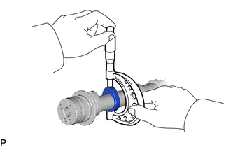
8. INSPECT CRANKSHAFT TIMING SPROCKET
| (a) Place the chain sub-assembly around the crankshaft timing sprocket. |
|
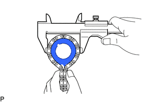
(b) Using a vernier caliper, measure the diameter of the crankshaft timing sprocket and chain sub-assembly.
Minimum Sprocket Diameter (with Chain Sub-assembly):
51.35 mm (2.02 in.)
NOTICE:
The vernier caliper must be in contact with the chain rollers when measuring.
HINT:
If the diameter is less than the minimum, replace the chain sub-assembly and crankshaft timing sprocket.
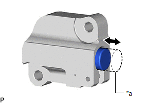
9. INSPECT NO. 1 CHAIN TENSIONER ASSEMBLY
| (a) Push the plunger and check that it moves smoothly. HINT: If the plunger does not move smoothly, replace the No. 1 chain tensioner assembly. |
|
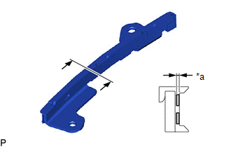
10. INSPECT CHAIN TENSIONER SLIPPER
| (a) Using a vernier caliper, measure the wear depth of the chain tensioner slipper. Maximum Depth: 1.0 mm (0.0394 in.) HINT: If the depth is more than the maximum, replace the chain tensioner slipper. |
|

11. INSPECT NO. 1 CHAIN VIBRATION DAMPER
| (a) Using a vernier caliper, measure the wear depth of the No. 1 chain vibration damper. Maximum Depth: 1.0 mm (0.0394 in.) HINT: If the depth is more than the maximum, replace the No. 1 chain vibration damper. |
|
12. INSPECT CYLINDER HEAD SET BOLT
(a) for 140 mm cylinder head set bolt:
| (1) Using a vernier caliper, measure the diameter of the threads at the measurement point. Standard Diameter: 10.7 to 10.9 mm (0.421 to 0.429 in.) Minimum Diameter: 10.6 mm (0.417 in.) Measurement Point (Distance from the Seat): 105 mm (4.134 in.) HINT:
|
|
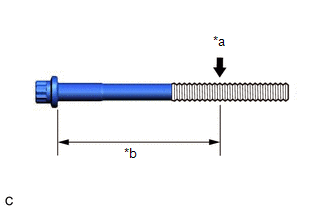
(b) for 130 mm cylinder head set bolt:
| (1) Using a vernier caliper, measure the diameter of the threads at the measurement point. Standard Diameter: 9.7 to 9.9 mm (0.382 to 0.390 in.) Minimum Diameter: 9.6 mm (0.378 in.) Measurement Point (Distance from the Seat): 115 mm (4.528 in.) HINT:
|
|

 Disassembly
DISASSEMBLY CAUTION / NOTICE / HINT NOTICE: This procedure includes the installation of small-head bolts. Refer to Small-Head Bolts of Basic Repair Hint to identify the small-head bolts...
 Reassembly
REASSEMBLY CAUTION / NOTICE / HINT NOTICE: This procedure includes the installation of small-head bolts. Refer to Small-Head Bolts of Basic Repair Hint to identify the small-head bolts...
Other information:
Toyota Yaris XP210 (2020-2026) Reapir and Service Manual: Components
C..
Toyota Yaris XP210 (2020-2026) Owner's Manual: Parking Brake
Setting the parking brake Depress the brake pedal and then firmly pull the parking brake lever fully upwards with sufficient force to hold the vehicle in a stationary position. Releasing the parking brake Depress the brake pedal and pull the parking brake lever upwards, then press the release button...
Categories
- Manuals Home
- Toyota Yaris Owners Manual
- Toyota Yaris Service Manual
- Opening and Closing the Liftgate/Trunk Lid
- Removal
- Power Integration No.1 System Missing Message (B235287,B235587,B235787-B235987)
- New on site
- Most important about car
Fuel Gauge
The fuel gauge shows approximately how much fuel is remaining in the tank when the ignition is switched ON. We recommend keeping the tank over 1/4 full.
