Toyota Yaris: Engine Unit / Reassembly
REASSEMBLY
CAUTION / NOTICE / HINT
NOTICE:
This procedure includes the installation of small-head bolts. Refer to Small-Head Bolts of Basic Repair Hint to identify the small-head bolts.
Click here

PROCEDURE
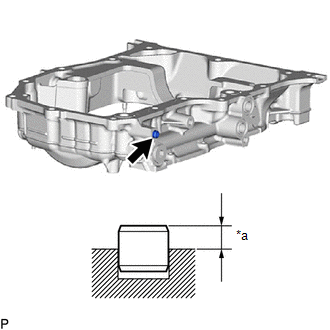
1. INSTALL RING PIN
NOTICE:
It is not necessary to remove the ring pins unless they are being replaced.
| (a) Using a plastic hammer, tap in new ring pin to the oil pan sub-assembly. Standard Protrusion Height: 3.0 to 5.0 mm (0.118 to 0.197 in.) |
|
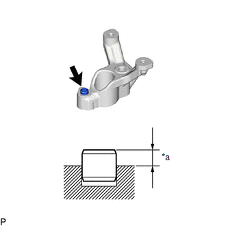
| (b) Using a plastic hammer, tap in new ring pin to the camshaft position sensor holder. Standard Protrusion Height: 3.5 to 4.5 mm (0.138 to 0.177 in.) |
|
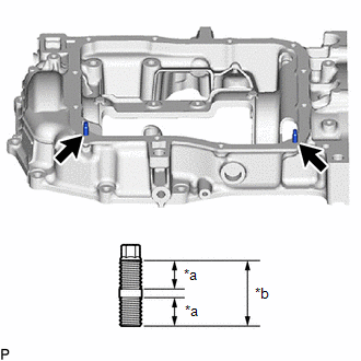
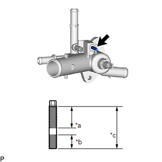
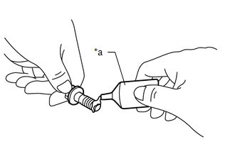
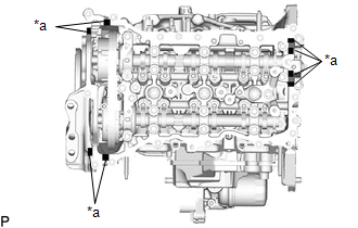
2. INSTALL STUD BOLT
NOTICE:
If a stud bolt is deformed or its threads are damaged, replace it.
| (a) Using an E6 "TORX" socket wrench, install the 2 stud bolts to the oil pan sub-assembly. Torque: 4.0 N·m {41 kgf·cm, 35 in·lbf} |
|
| (b) Using an E6 "TORX" socket wrench, install the stud bolt to the camshaft bearing cap. Torque: 4.0 N·m {41 kgf·cm, 35 in·lbf} |
|
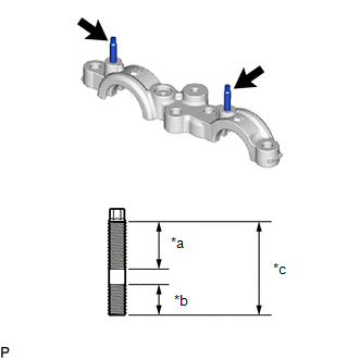
| (c) Using an E6 "TORX" socket wrench, install the stud bolt to the water outlet sub-assembly. Torque: 4.0 N·m {41 kgf·cm, 35 in·lbf} |
|
3. INSPECT BALANCESHAFT BACKLASH
Click here

4. INSTALL REAR ENGINE OIL SEAL
Click here

5. INSTALL BALANCESHAFT HOUSING SPACER
| (a) Install the balanceshaft housing spacer to the crankshaft bearing cap sub-assembly. |
|
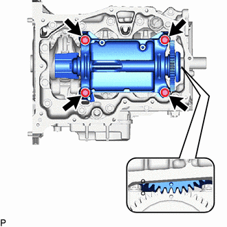
6. INSTALL ENGINE BALANCER ASSEMBLY
| (a) Install the new o-ring to the crankshaft bearing cap sub-assembly. |
|
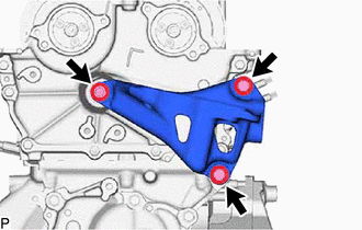
| (b) Install the engine balancer assembly to the crankshaft bearing cap sub-assembly with the 4 bolts. Torque: 1st : 43 N·m {438 kgf·cm, 32 ft·lbf} 2nd : 54 N·m {551 kgf·cm, 40 ft·lbf} |
|
7. INSTALL OIL STRAINER SUB-ASSEMBLY
(a) Apply a light coat of engine oil to a new oil strainer gasket.
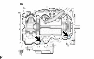
| (b) Install the oil strainer sub-assembly and oil strainer gasket to the stiffening crankcase assembly with the 2 bolts. Torque: 10 N·m {102 kgf·cm, 7 ft·lbf} |
|
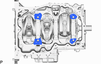
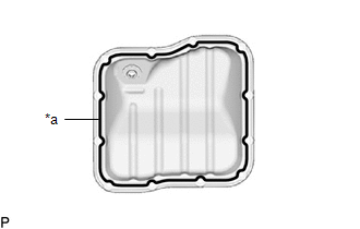
8. INSTALL OIL PAN SUB-ASSEMBLY
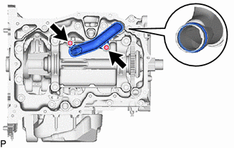
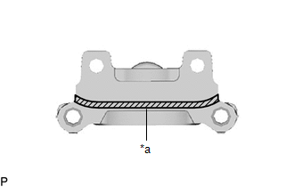
| (a) Apply seal packing in a continuous line as shown in the illustration. Seal Packing: Toyota Genuine Seal Packing Black, Three Bond 1207B or equivalent Standard Seal Packing Dimension:
NOTICE:
|
|
| (b) Install the 2 new o-ring to the crankshaft bearing cap assembly. |
|
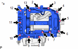
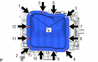
| (c) Temporarily install the oil pan sub-assembly with the 13 bolts. Bolt Length :
|
|

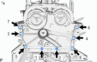
| (d) Tighten the 13 bolts in the order shown in the illustration to install the oil pan sub-assembly. Torque: 25 N·m {255 kgf·cm, 18 ft·lbf} |
|
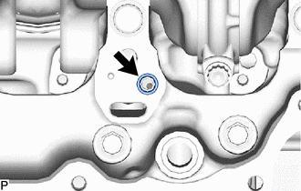
9. INSTALL NO. 1 OIL PAN PLUG
(a) Install a new gasket and the No. 1 oil pan plug to the oil pan sub-assembly.
Torque:
44 N·m {449 kgf·cm, 32 ft·lbf}
10. INSTALL NO. 2 OIL PAN SUB-ASSEMBLY
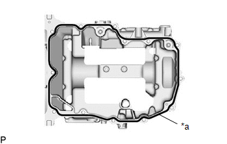
| (a) Apply seal packing in a continuous line as shown in the illustration. Seal Packing: Toyota Genuine Seal Packing Black, Three Bond 1207B or equivalent Standard Seal Packing Dimension: 2.5 to 3.5 mm (0.0984 to 0.138 in.) NOTICE:
|
|
| (b) Install the No. 2 oil pan sub-assembly with the 9 bolts and 2 nuts in several steps in the order shown in the illustration. Torque: 10 N·m {102 kgf·cm, 7 ft·lbf} |
|
11. INSTALL OIL PAN DRAIN PLUG
(a) Install a new gasket and the oil pan drain plug to the oil pan sub-assembly.
Torque:
40 N·m {408 kgf·cm, 30 ft·lbf}
12. INSTALL OIL FILTER BRACKET SUB-ASSEMBLY
(a) Install a 2 new gasket and the oil filter bracket sub-assembly to the oil pan sub-assembly.
Torque:
21 N·m {214 kgf·cm, 15 ft·lbf}
13. INSTALL OIL COOLER ASSEMBLY
Click here

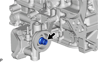
14. INSTALL OIL FILTER UNION
| (a) Using a 12 mm hexagon socket wrench, install the oil filter union to the stiffening crankcase assembly. Torque: 29.5 N·m {301 kgf·cm, 22 ft·lbf} |
|
15. INSTALL OIL FILTER SUB-ASSEMBLY
Click here

16. INSTALL CYLINDER HEAD GASKET
Click here

17. INSTALL CYLINDER HEAD SUB-ASSEMBLY
HINT:
The cylinder head set bolts are tightened in 3 progressive steps.
(a) Place the cylinder head sub-assembly on the cylinder block sub-assembly.
NOTICE:
- Ensure that the contact surface of the cylinder head sub-assembly is free of oil.
- Place the cylinder head sub-assembly on the cylinder block sub-assembly gently in order not to damage the cylinder head gasket with the bottom of the cylinder head sub-assembly.
(b) Install the 8 plate washers to the 8 cylinder head set bolts.
(c) Apply a light coat of engine oil to the threads and under the heads of the cylinder head set bolts.
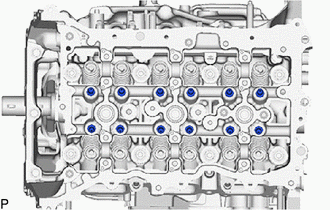
(d) Install the 8 cylinder head set bolts and 3 boltsto the cylinder head sub-assembly.

 | Front of Engine |
Bolt Diameter:
| Item | Diameter |
|---|---|
| Bolt (A) | 10 mm (0.394 in.) |
| Bolt (B) | 11 mm (0.433 in.) |
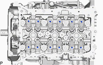
(e) Step 1:
(1) Using a 12 mm socket wrench, install and uniformly tighten the 8 cylinder head set bolts in several steps in the order shown in the illustration.
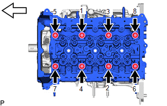
 | Front of Engine |
NOTICE:
Be careful not to drop the plate washers into the cylinder head sub-assembly.
Torque:
Bolt (A) :
40 N·m {408 kgf·cm, 30 ft·lbf}
Bolt (B) :
50 N·m {510 kgf·cm, 37 ft·lbf}
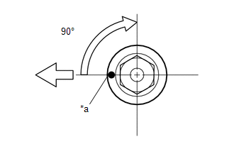
(f) Step 2:
(1) Mark each cylinder head set bolt head with paint as shown in the illustration.
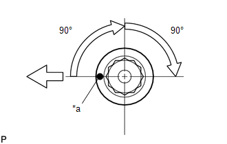
| *a | Paint Mark |
 | Front of Engine |
(2) Tighten the cylinder head set bolts 90° in the order shown in step 1.
(g) Step 3:
(1) Tighten the cylinder head set bolts another 90° in the order shown in step 1.
(2) Check that the paint marks are now facing rearward.
HINT:
Perform inspection after repair after replacing the cylinder head sub-assembly.
Click here

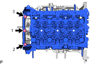
| (h) Install the 3 bolts in the order shown in the illustration. Torque: 25 N·m {255 kgf·cm, 18 ft·lbf} |
|
18. INSTALL VALVE STEM CAP
(a) Apply a light coat of engine oil to the valve stem cap ends.
| (b) Install the 12 valve stem caps to the cylinder head sub-assembly. NOTICE:
|
|
19. INSTALL VALVE LASH ADJUSTER ASSEMBLY
(a) Inspect the 12 valve lash adjuster assemblies before installing them.
Click here

| (b) Install the 12 valve lash adjuster assemblies to the cylinder head sub-assembly. NOTICE: Install the same parts in the same combination to their original locations. |
|
20. INSTALL NO. 1 VALVE ROCKER ARM SUB-ASSEMBLY
| (a) Apply engine oil to the valve lash adjuster assembly tips and valve stem caps. |
|
(b) Install the 12 No. 1 valve rocker arm sub-assemblies as shown in the illustration.
NOTICE:
Install the same parts in the same combination to their original locations.
21. INSTALL NO. 1 CAMSHAFT BEARING CAP
(a) Install the No. 1 camshaft bearing cap to the cylinder head sub-assembly.
22. INSTALL EXHAUST CAMSHAFT SUB-ASSEMBLY
HINT:
Perform inspection after repair after replacing the exhaust camshaft sub-assembly.
Click here

(a) Clean the camshaft journals and camshaft bearing caps.
(b) Apply a light coat of engine oil to the camshaft journals and camshaft bearing caps.
(c) Install the exhaust camshaft sub-assembly to the camshaft bearing caps.
23. INSTALL INTAKE CAMSHAFT SUB-ASSEMBLY
HINT:
Perform inspection after repair after replacing the intake camshaft sub-assembly.
Click here

(a) Clean the camshaft journals and camshaft bearing caps.
(b) Apply a light coat of engine oil to the camshaft journals, camshaft bearing caps.
(c) Install the intake camshaft sub-assembly to the camshaft bearing caps.
24. INSTALL CAMSHAFT BEARING CAP
| (a) Set the No. 2 camshaft bearing cap and 6 No. 4 camshaft bearing caps. Installation Position of No. 2 Camshaft Bearing Cap:
|
|
| (b) Install and uniformly tighten the 16 bolts. Torque: 18 N·m {184 kgf·cm, 13 ft·lbf} Bolt Length:
|
|
(c) Check the torque of each bolt again.
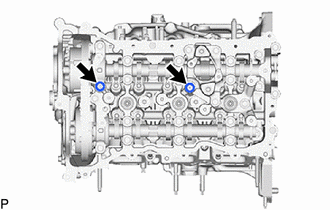
25. TEMPORARILY TIGHTEN CAMSHAFT POSITION SENSOR HOLDER
(a) Temporarily tighten the camshaft position sensor holder with the bolt.
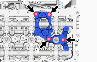
26. INSTALL FUEL PUMP LIFTER HOUSING
| (a) Install the 3 bolts in the order shown in the illustration. Torque: 21 N·m {214 kgf·cm, 15 ft·lbf} |
|
27. INSTALL FUEL PUMP LIFTER GUIDE
(a) Install the fuel pump lifter guide with the 2 bolts.
Torque:
10 N·m {102 kgf·cm, 7 ft·lbf}
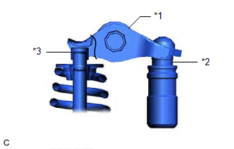
28. INSTALL CAMSHAFT TIMING GEAR ASSEMBLY
HINT:
Perform inspection after repair after replacing the camshaft timing gear assembly.
Click here

| (a) Align and fit the knock pin of the intake camshaft sub-assembly to the knock pin hole of the camshaft timing gear assembly. |
|
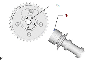
| (b) Using a wrench, hold the hexagonal portion of the intake camshaft sub-assembly. NOTICE:
|
|
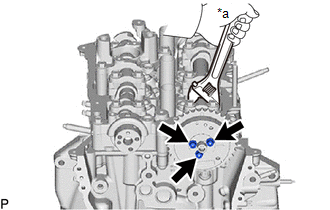
(c) Using a 5 mm hexagon socket wrench, install the camshaft timing gear assembly with the 3 bolts and install the camshaft timing oil control valve assembly (intake camshaft timing gear bolt assembly).
Torque:
19 N·m {194 kgf·cm, 14 ft·lbf}
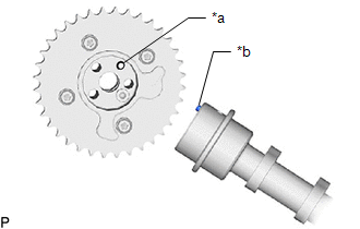
29. INSTALL CAMSHAFT TIMING EXHAUST GEAR ASSEMBLY
HINT:
Perform inspection after repair after replacing the camshaft timing exhaust gear assembly.
Click here

| (a) Align and fit the knock pin of the exhaust camshaft sub-assembly to the knock pin hole of the camshaft timing exhaust gear assembly. |
|
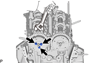
(b) Using a wrench, hold the hexagonal portion of the exhaust camshaft sub-assembly.
NOTICE:
- Be careful not to damage the cylinder head sub-assembly or spark plug tube with the wrench.
- Do not disassemble the camshaft timing exhaust gear assembly.
| (c) Using a 5 mm hexagon socket wrench, install the camshaft timing exhaust gear assembly with the 3 bolts and install the camshaft timing oil control valve assembly (exhaust camshaft timing gear bolt assembly). Torque: 19 N·m {194 kgf·cm, 14 ft·lbf} |
|
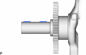
30. INSTALL CRANKSHAFT TIMING GEAR KEY
| (a) Using a plastic hammer, tap in the 2 crankshaft timing gear keys. HINT: Tap in the crankshaft timing gear keys until they contact the crankshaft as shown in the illustration. |
|
31. INSTALL CRANKSHAFT TIMING GEAR OR SPROCKET
(a) Install the crankshaft timing gear or sprocket to the crankshaft.
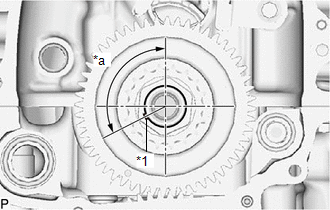
32. SET NO. 1 CYLINDER TO TDC (COMPRESSION)
(a) Temporarily install the crankshaft pulley bolt.
| (b) Rotate the crankshaft 117.11° counterclockwise to position the crankshaft timing gear key as shown in the illustration. |
|
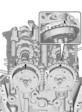
| (c) Check that the timing marks of the camshaft timing exhaust gear assembly and camshaft timing gear assembly are as shown in the illustration. |
|
33. INSTALL NO. 1 CHAIN VIBRATION DAMPER
(a) Install the No. 1 chain vibration damper with the 2 bolts.
Torque:
24 N·m {245 kgf·cm, 18 ft·lbf}
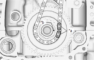
34. INSTALL CHAIN SUB-ASSEMBLY
(a) Remove the crankshaft pulley bolt.
| (b) Align the paint mark (pink) of the chain sub-assembly with the timing mark of the canshaft ttiming gear assembly, camshaft timing exhaust gear assembly and install the chain sub-assembly to the canshaft ttiming gear assembly and camshaft timing exhaust gear assembly. |
|
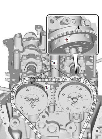
| (c) Align the paint mark (yellow) of the chain sub-assembly with the timing mark of the crankshaft timing sprocket and install the chain sub-assembly to the crankshaft timing sprocket. |
|
35. INSTALL CHAIN TENSIONER SLIPPER
(a) Install the chain tensioner slipper with the bolt.
Torque:
21 N·m {214 kgf·cm, 15 ft·lbf}
36. INSTALL DAMPER PLATE SPACER
(a) Install the damper plate spacer to the No. 2 camshaft bearing cap.
37. INSTALL TIMING CHAIN GUIDE
(a) Install the timing chain guide with the 2 nuts.
Torque:
10 N·m {102 kgf·cm, 7 ft·lbf}
38. INSTALL NO. 1 CHAIN TENSIONER ASSEMBLY
HINT:
After replacing or removing and installing the No. 1 chain tensioner assembly, an abnormal noise may occur at start up until the oil in the line has had time to replenish.
(a) Install the No. 1 chain tensioner assembly with the 2 bolts.
Torque:
10 N·m {102 kgf·cm, 7 ft·lbf}
(b) Remove the hexagon wrench.
39. SET NO. 1 CYLINDER TO TDC (COMPRESSION)
Click here

40. INSTALL TIMING CHAIN COVER ASSEMBLY
Click here

41. INSTALL TIMING CHAIN COVER OIL SEAL
Click here

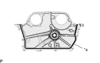
42. INSTALL NO. 2 TIMING CHAIN COVER ASSEMBLY
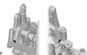
| (a) Apply seal packing in a continuous line as shown in the illustration. Seal Packing: Toyota Genuine Seal Packing Black, Three Bond 1207B or equivalent Standard Seal Packing Dimension:
NOTICE:
|
|
| (b) Apply adhesive to 2 or 3 threads at the end of each of the 2 bolts (B). Adhesive: Toyota Genuine Adhesive 1324, Three Bond 1324 or equivalent |
|
| (c) Temporarily tighten the No. 2 timing chain assembly with the 8 bolts. |
|
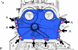
| (d) Tighten the 8 bolts in the order shown in the illustration. Torque: 12 N·m {122 kgf·cm, 9 ft·lbf} |
|
| (e) Install the engine mounting bracket RH with the 3 bolts in the order shown in the illustration. Torque: 43 N·m {438 kgf·cm, 32 ft·lbf} NOTICE: After applying seal packing to the No. 2 timing chain cover assembly, install the engine mounting bracket RH within 10 minutes. |
|
43. INSTALL NO. 1 VACUUM PUMP BRACKET
| (a) Apply seal packing in a continuous line as shown in the illustration. Seal Packing: Toyota Genuine Seal Packing Black, Three Bond 1207B or equivalent Standard Seal Packing Dimension:
NOTICE:
|
|
(b) Install the No. 1 vacuum pump bracket with the 4 bolts.
Torque:
21 N·m {214 kgf·cm, 15 ft·lbf}
| (c) Wipe off any excess seal packing. |
|
44. INSTALL SPARK PLUG TUBE GASKET
(a) Install 3 new spark plug tube gaskets to the cylinder head cover sub-assembly.
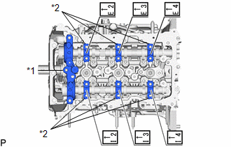
45. INSTALL CYLINDER HEAD COVER SUB-ASSEMBLY
| (a) Install a new 2 camshaft bearing cap oil hole gaskets to the No. 2 camshaft bearing cap and fuel pump lifter housing. NOTICE: Remove any oil from the contact surfaces. |
|
(b) Install 5 new cylinder head cover gaskets to the cylinder head cover sub-assembly.
NOTICE:
Remove any oil from the contact surfaces.
(c) Apply seal packing as shown in the illustration.
| *a | Seal Packing Diameter: 3.0 to 6.0 mm (0.118 to 0.236 in.) |
 | Seal Packing |
Seal Packing:
Toyota Genuine Seal Packing Black, Three Bond 1207B or equivalent
Standard Seal Packing Diameter:
3.0 to 6.0 mm (0.118 to 0.236 in.)
NOTICE:
- Remove any oil from the contact surfaces.
- Install the cylinder head cover sub-assembly within 3 minutes and tighten the bolts within 15 minutes of applying seal packing.
- Do not start the engine for at least 2 hours after installation.
| (d) Apply adhesive to 2 or 3 threads at the end of each of the bolt (D). Adhesive: Toyota Genuine Adhesive 1324, Three Bond 1324 or equivalent |
|

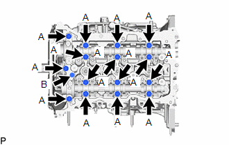
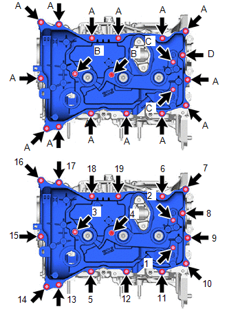
| (e) Install the 2 camshaft position sensors (for Exhaust Side and for Intake Side) and cylinder head cover sub-assembly with 2 bolts (B) and the 11 bolts (A,D) and 2 bolts (C) in the order shown in the illustration. Bolt Length:
Torque: 10 N·m {102 kgf·cm, 7 ft·lbf} NOTICE:
|
|
46. INSTALL OUTLET WATER SUB-ASSEMBLY
(a) Install the outlet water sub-assembly and a new outlet water gasket to the cylinder head sub-assembly with the 2 nuts.
Torque:
10 N·m {102 kgf·cm, 7 ft·lbf}
47. INSTALL CRANKSHAFT PULLEY ASSEMBLY
| (a) Align the crankshaft timing gear key with the key groove of the crankshaft pulley assembly. |
|
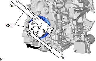
(b) Using SST, hold the crankshaft pulley assembly and install the crankshaft pulley set bolt.
SST: 09213-54015
SST: 09330-00021
Torque:
260 N·m {2651 kgf·cm, 192 ft·lbf}
(c) Mark each crankshaft pulley set bolt with paint as shown in the illustration.
| *a | Paint Mark |
 | Front of Engine |
(d) Tighten the crankshaft pulley set bolt 90°.
48. INSTALL VACUUM PUMP ASSEMBLY
Click here

49. INSTALL PCV VALVE (VENTILATION VALVE SUB-ASSEMBLY)
Click here

50. INSTALL CRANKSHAFT POSITION SENSOR
Click here

51. INSTALL OIL FILLER CAP GASKET
(a) Install a new oil filler cap gasket to the oil filler cap sub-assembly.
52. INSTALL OIL FILLER CAP ASSEMBLY
(a) Install the oil filler cap sub-assembly to the cylinder head cover sub-assembly.
53. INSTALL ENGINE WATER PUMP ASSEMBLY (WATER INLET HOUSING)
Click here

54. INSTALL WATER INLET WITH THERMOSTAT SUB-ASSEMBLY
Click here

55. INSTALL CAMSHAFT TIMING OIL CONTROL SOLENOID ASSEMBLY (for Intake Side)
Click here

56. INSTALL CAMSHAFT TIMING OIL CONTROL SOLENOID ASSEMBLY (for Exhaust Side)
Click here

57. INSTALL OIL PRESSURE AND TEMPERATURE SENSOR
Click here

58. INSTALL SPARK PLUG
Click here

 Inspection
INSPECTION PROCEDURE 1. INSPECT NO. 1 VALVE ROCKER ARM SUB-ASSEMBLY (a) Turn the roller by hand to check that it turns smoothly. HINT: If the roller does not turn smoothly, replace the No...
 Installation
INSTALLATION CAUTION / NOTICE / HINT NOTICE: This procedure includes the installation of small-head bolts. Refer to Small-Head Bolts of Basic Repair Hint to identify the small-head bolts...
Other information:
Toyota Yaris XP210 (2020-2026) Reapir and Service Manual: Brake Switch "A" Signal Compare Failure (P057162)
DESCRIPTION When the brake pedal is depressed, the stop light switch assembly outputs a signal to the ECM. The ECM uses this signal to control cancellation of vehicle speed by the dynamic radar cruise control. When the ECM determines that terminals STP and ST1- of the stop light switch assembly are both less than 1 V, DTC P057162 is stored...
Toyota Yaris XP210 (2020-2026) Reapir and Service Manual: Inspection
INSPECTION PROCEDURE 1. INSPECTION AFTER COLLISION (a) Inspect the SRS parts in table below. CAUTION: Be sure to read Precaution thoroughly before servicing. Click here Be sure to correctly follow the removal and installation procedures for the SRS parts...
Categories
- Manuals Home
- Toyota Yaris Owners Manual
- Toyota Yaris Service Manual
- How to use USB mode
- Brake System Control Module "A" System Voltage System Voltage Low (C137BA2)
- Immobilizer System
- New on site
- Most important about car
Break-In Period
No special break-in is necessary, but a few precautions in the first 600 miles (1,000 km) may add to the performance, economy, and life of the vehicle.
Do not race the engine. Do not maintain one constant speed, either slow or fast, for a long period of time. Do not drive constantly at full-throttle or high engine rpm for extended periods of time. Avoid unnecessary hard stops. Avoid full-throttle starts.