Toyota Yaris: Engine Unit / Installation
INSTALLATION
CAUTION / NOTICE / HINT
NOTICE:
This procedure includes the installation of small-head bolts. Refer to Small-Head Bolts of Basic Repair Hint to identify the small-head bolts.
Click here

PROCEDURE
1. INSTALL TIMING GEAR COVER INSULATOR
(a) Install the timing gear cover insulator to the cylinder blocke sub-assembly.
2. INSTALL NO. 3 CYLINDER BLOCK INSULATOR
(a) Install the No. 3 cylinder block insulator to the oil pan sub-assembly.
3. INSTALL INTAKE PIPE OR HOSE STAY
(a) Install the intake pipe or hose stay to the cylinder head cover sub-aseembly with the 3 bolts.
Torque:
10 N·m {102 kgf·cm, 7 ft·lbf}
4. INSTALL FUEL HOSE BRACKET
(a) Install the fuel hose bracket to the cylinder head cover sub-aseembly with the 2 bolts.
Torque:
10 N·m {102 kgf·cm, 7 ft·lbf}
5. INSTALL ENGINE COVER BRACKET
(a) Install the engine cover bracket to the vacuum pump bracket with the bolt.
Torque:
21 N·m {214 kgf·cm, 15 ft·lbf}
6. INSTALL ENGINE COVER JOINT
(a) Install the engine cover joint to the cylinder head cover sub-aseembly and vacuum pump bracket.
Torque:
10 N·m {102 kgf·cm, 7 ft·lbf}
7. INSTALL IGNITION COIL ASSEMBLY
Click here

8. INSTALL VACUUM REGULATING VALVE ASSEMBLY
(a) Install the vacuum regulating valve assembly to the cylinder head cover sub-assembly with the 2 bolts.
Torque:
10 N·m {102 kgf·cm, 7 ft·lbf}
9. INSTALL VENTILATION HOSE
(a) Connect the No. 2 ventilation hose to the cylinder head cover sub-assembly and slide the clip to secure it.
(b) Engage the clamp.
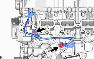
10. INSTALL SENSOR WIRE
| (a) Install the sensor wire to the cylinder head sub-assembly and cylinder block sub-aseembly with the 2 bolts. Torque: Bolt (A) : 10 N·m {102 kgf·cm, 7 ft·lbf} Bolt (B) : 21 N·m {214 kgf·cm, 15 ft·lbf} |
|
11. INSTALL NO. 2 CYLINDER BLOCK INSULATOR
(a) Install the No. 2 cylinder block insulator to the cylinder block sub-assembly.
12. INSTALL FUEL INJECTOR SEAL
Click here

13. INSTALL FUEL INJECTOR ASSEMBLY
Click here

14. INSTALL NO. 6 ENGINE WIRE
Click here

15. INSTALL FUEL DELIVERY PIPE
Click here

16. TEMPORARILY INSTALL FUEL (ENGINE ROOM SIDE) PUMP ASSEMBLY
Click here

17. INSTALL FUEL (ENGINE ROOM SIDE) PUMP ASSEMBLY
Click here

18. INSTALL NO. 1 FUEL PIPE SUB-ASSEMBLY
Click here

19. INSTALL INJECTOR VIBRATION INSULATOR
Click here

20. INSTALL FUEL DELIVERY SPACER
Click here

21. INSTALL FUEL DELIVERY PIPE (for Low Pressure)
Click here

22. INSTALL NO. 1 DELIVERY PIPE SPACER
(a) Install the No. 1 fuel delivery spacer to the cylinder head sub-asembly.
23. INSTALL FUEL DELIVERY GUARD
Click here

24. INSTALL OIL LEVEL GAUGE GUIDE
Click here

25. INSTALL OIL LEVEL GAUGE SUB-ASSEMBLY
Click here

26. INSTALL FUEL TUBE SUB-ASSEMBLY
(a) Install the fuel tube sub-assembly
Click here

(b) Install the bolt.
(c) Install the fuel pipe clamp to the fuel tube connector.
27. INSTALL NO. 7 ENGINE WIRE
(a) Connect the 2 connectors and install the No. 7 engine wire.
(b) Engage the clamp.
28. INSTALL WATER BY-PASS PIPE
(a) Install the water by-pass pipe to the engine assembly and slide the clip to secure it.
(b) Install the bolt and nut.
Torque:
10 N·m {102 kgf·cm, 7 ft·lbf}
29. INSTALL INTAKE MANIFOLD
Click here

30. INSTALL INTAKE AIR CONNECTOR BRACKET
Click here

31. INSTALL NO. 2 ENGINE COVER BRACKET
(a) Install the No. 2 engine cover bracket to the intake manifold with the bolt.
Torque:
10 N·m {102 kgf·cm, 7 ft·lbf}
32. INSTALL NO. 6 ENGINE WIRE
(a) Engage the 5 clamps and connect the No. 6 engine wire.
33. INSTALL PURGE VALVE (PURGE VSV)
Click here

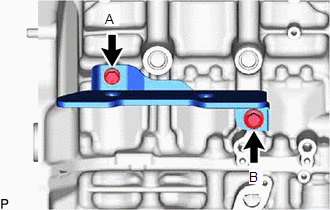
34. INSTALL NO. 2 TURBO INSULATOR
| (a) Install the No. 2 turbo insulator to the cylinder brock sub-assembly with the 2 bolts. Torque: Bolt (A) : 21 N·m {214 kgf·cm, 15 ft·lbf} Bolt (B) : 30 N·m {306 kgf·cm, 22 ft·lbf} |
|
35. INSTALL TURBOCHARGER SUB-ASSEMBLY
| (a) Install the turbocharger sub-aseembly to the cylinder head sub-aseembly wuth the 7 nuts. Torque: Nut (B) : 44.3 N·m {452 kgf·cm, 33 ft·lbf} |
|
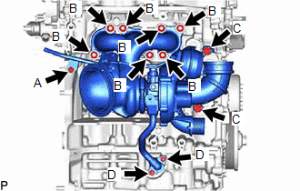
(b) Connect the No. 1 turbo water pipe sub-assembly with the 2 bolts.
Torque:
Bolt (A) :
13 N·m {133 kgf·cm, 10 ft·lbf}
Bolt (C) :
35 N·m {357 kgf·cm, 26 ft·lbf}
(c) Install the inlet turbo oil pipe union bolt.
Torque:
Bolt (C) :
35 N·m {357 kgf·cm, 26 ft·lbf}
(d) Connect the outlet turbo oil pipe with the 2 bolts.
Torque:
Bolt (D) :
13 N·m {133 kgf·cm, 10 ft·lbf}
36. INSTALL NO. 1 TURBO INSULATOR
Click here

37. INSTALL NO. 4 CYLINDER BROCK INSULATOR
(a) Install the No. 4 cylinder brock insulator with the 2 bolts.
Torque:
10 N·m {102 kgf·cm, 7 ft·lbf}
38. INSTALL DRIVE SHAFT BEARING BRACKET
(a) Install the drive shaft bearing bracket to the cylinder block sub-aseembly with the 3 bolts.
Torque:
63.7 N·m {650 kgf·cm, 47 ft·lbf}
39. INSTALL ENGINE HANGER BRACKET
(a) Install the engine hanger bracket to the cylinder head sub-assembly with the 2 bolts.
Torque:
43 N·m {438 kgf·cm, 32 ft·lbf}
40. INSTALL INTAKE AIR PIPE
(a) Install the intake air pipe and tighten the hose clamp.
(b) Install the 3 bolts.
(c) Connect the ventilation hose.
(d) Connect the No. 2 vaccum transmitting hose.
(e) Connect the No. 1 vaccum transmitting hose.
41. INSTALL WATER BY-PASS HOSE ASSEMBLY
(a) Install the water by-pass hose assembly and slide the clip to secure it.
(b) Engage the clamp.
42. INSTALL NO. 4 WATER BY-PASS PIPE
(a) Install the No. 4 water by-pass pipe and slide the clip to secure it.
(b) Connect the No. 4 water by-pass pipe with the 3 bolts.
43. INSTALL NO. 3 WATER BY-PASS PIPE
(a) Install the No. 3 water by-pass pipe and slide the clip to secure it.
(b) Connect the No. 3 water by-pass pipe with the bolt.
Torque:
10 N·m {102 kgf·cm, 7 ft·lbf}
44. INSTALL NO. 1 WATER BY-PASS PIPE
(a) Install the No. 1 water by-pass pipe and slide the clip to secure it.
(b) Connect the No. 1 water by-pass pipe with the bolt and nut.
Torque:
10 N·m {102 kgf·cm, 7 ft·lbf}
45. INSTALL NO. 1 TURBO WATER HOSE
(a) Install the No. 1 turbo water hose and slide the 2 clips to secure it.
46. INSTALL UNION TO CONNECTOR TUBE HOSE
Click here

47. INSTALL NO. 3 VACUUM TRANSMITTING HOSE
(a) Install the No. 3 vacuum transmitting hose.
(b) Engage the 2 clamps.
48. INSTALL NO. 5 WATER BY-PASS HOSE
(a) Install the No. 5 water by-pass hose and slide the 2 clips to secure it.
(b) Install the bolt.
Torque:
10 N·m {102 kgf·cm, 7 ft·lbf}
49. INSTALL NO. 6 WATER BY-PASS HOSE
(a) Install the No. 6 water by-pass hose and slide the 2 clips to secure it.
(b) Engage the clamp.
50. INSTALL NO. 5 AIR HOSE
(a) Install the No. 5 air hose and tighten the hose clamp.
Torque:
6.0 N·m {61 kgf·cm, 53 in·lbf}
51. INSTALL NO. 2 AIR HOSE
(a) Install the No. 2 air hose and tighten the hose clamp.
Torque:
6.0 N·m {61 kgf·cm, 53 in·lbf}
52. INSTALL OUTLET HEATER WATER HOSE
(a) Install the outlet heater water hose and slide the clip to secure it.
53. INSTALL INLET HEATER WATER HOSE
(a) Install the inlet heater water hose and slide the clip to secure it.
54. INSTALL FUEL TUBE SUB-ASSEMBLY
(a) Install the fuel tube sub-aseembly to the fuel pipe sub-aseembly.
Click here

(b) Engage the clamp.
55. INSTALL COMPRESSOR WITH PULLEY ASSEMBLY
Click here

 Reassembly
REASSEMBLY CAUTION / NOTICE / HINT NOTICE: This procedure includes the installation of small-head bolts. Refer to Small-Head Bolts of Basic Repair Hint to identify the small-head bolts...
 Front Crankshaft Oil Seal
ComponentsCOMPONENTS ILLUSTRATION
*1 NO. 1 ENGINE UNDER COVER ASSEMBLY *2 ENGINE UNDER COVER RH *3 FAN AND GENERATOR V BELT *4 CRANKSHAFT PULLEY ASSEMBLY *5 TIMING CHAIN COVER OIL SEAL *6 CRANKSHAFT PULLEY SET BOLT
Tightening torque for "Major areas involving basic vehicle performance such as moving/turning/stopping" : N*m (kgf*cm, ft...
Other information:
Toyota Yaris XP210 (2020-2026) Owner's Manual: Spare Tire
Your Toyota has a temporary spare tire. The temporary spare tire is lighter and smaller than a conventional tire, and is designed only for emergency use and should be used only for VERY short periods. Temporary spare tires should NEVER be used for long drives or extended periods...
Toyota Yaris XP210 (2020-2026) Owner's Manual: Starting the Engine
Make sure you are carrying the key. Occupants should fasten their seat belts. Make sure the parking brake is on. Continue to press the brake pedal firmly until the engine has completely started. Manual transaxle:Continue to press the clutch pedal firmly until the engine has completely started...
Categories
- Manuals Home
- Toyota Yaris Owners Manual
- Toyota Yaris Service Manual
- Removal
- Adjustment
- Diagnostic Trouble Code Chart
- New on site
- Most important about car
Supplemental Restraint System (SRS) Precautions
The front and side supplemental restraint systems (SRS) include different types of air bags. Please verify the different types of air bags which are equipped on your vehicle by locating the “SRS AIRBAG” location indicators. These indicators are visible in the area where the air bags are installed.
The air bags are installed in the following locations:
The steering wheel hub (driver air bag) The front passenger dashboard (front passenger air bag) The outboard sides of the front seatbacks (side air bags) The front and rear window pillars, and the roof edge along both sides (curtain air bags)