Toyota Yaris: Manual Transaxle System / Clutch Position Sensor "A"Circuit Short to Battery (P080512,P080514)
DESCRIPTION
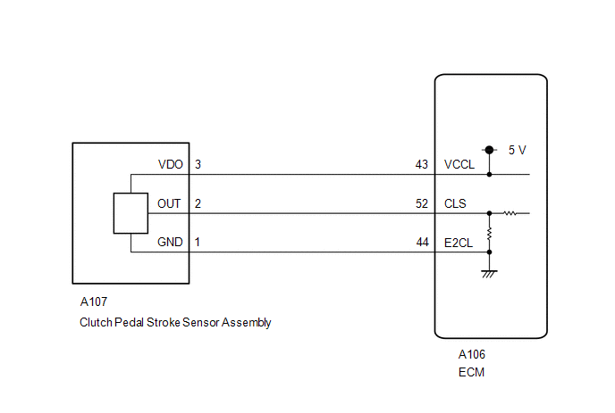
The clutch pedal stroke sensor assembly is mounted on the clutch pedal, and detects the clutch pedal position and sends signals to the ECM.
| DTC No. | Detection Item | DTC Detection Condition | Trouble Area | MIL | Memory | Note |
|---|---|---|---|---|---|---|
| P080512 | Clutch Position Sensor "A"Circuit Short to Battery | Clutch stroke sensor signal voltage is 4.8 V or more for 0.5 seconds or more (1 trip detection logic) |
| Does not come on | DTC stored | SAE Code: P0808 |
| P080514 | Clutch Position Sensor "A"Circuit Short to Ground or Open | Clutch stroke sensor signal voltage is 0.2 V or less for 0.5 seconds or more (1 trip detection logic) |
| Does not come on | DTC stored | SAE Code: P0807 |
CONFIRMATION DRIVING PATTERN
HINT:
After repairs have been completed, clear the DTCs and then check that the vehicle has returned to normal by performing the following All Readiness check procedure.
- Clear the DTCs (even if no DTCs are stored, perform the clear DTC procedure).
- Turn the ignition switch off and wait for at least 30 seconds.
- Turn the ignition switch to ON and wait for 3 seconds or more.
- Enter the following menus: Powertrain / Engine / Utility / All Readiness.
- Input the DTC: P080512 or P080514.
-
Check the DTC judgment result.
GTS Display
Description
NORMAL
- DTC judgment completed
- System normal
ABNORMAL
- DTC judgment completed
- System abnormal
INCOMPLETE
- DTC judgment not completed
- Perform driving pattern after confirming DTC enabling conditions
N/A
- Unable to perform DTC judgment
- Number of DTCs which do not fulfill DTC preconditions has reached ECU memory limit
HINT:
- If the judgment result shows NORMAL, the system is normal.
- If the judgment result shows ABNORMAL, the system has a malfunction.
- If the judgment result shows INCOMPLETE or N/A, perform the Confirmation Driving Pattern and check the DTC judgment result again.
WIRING DIAGRAM
PROCEDURE
| 1. | READ VALUE USING GTS (CLUTCH STROKE SENSOR VOLTAGE) |
(a) Enter the following menus.
Powertrain > Engine > Data List| Tester Display |
|---|
| Clutch Stroke Sensor Voltage |
(b) Read the values displayed on the GTS.
Standard Voltage:
| GTS Display | Condition | Specified Condition |
|---|---|---|
| CLUTCH STROKE SENSOR VOLTAGE | Clutch pedal fully released | 0.5 to 1.1 V |
| Clutch pedal fully depressed | 2.6 to 4.5 V |
| OK |
 | CHECK FOR INTERMITTENT PROBLEMS |
|

| 2. | CHECK TERMINAL VOLTAGE (POWER SOURCE OF CLUTCH PEDAL STROKE SENSOR ASSEMBLY) |
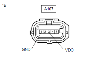
| (a) Disconnect the clutch pedal stroke sensor assembly connector. |
|
(b) Turn the ignition switch to ON.
(c) Measure the voltage according to the value(s) in the table below.
Standard Voltage:
| Tester Connection | Switch Condition | Specified Condition |
|---|---|---|
| A107-3 (VDO) - A107-1 (GND) | Ignition switch ON | 4.5 to 5.5 V |
| NG |
 | GO TO STEP 6 |
|

| 3. | CHECK HARNESS AND CONNECTOR (CLUTCH PEDAL STROKE SENSOR ASSEMBLY - ECM) |
(a) Disconnect the A106 ECM connector.
(b) Disconnect the A107 clutch pedal stroke sensor assembly connector.
(c) Measure the resistance according to the value(s) in the table below.
Standard Resistance:
| Tester Connection | Condition | Specified Condition |
|---|---|---|
| A107-2 (OUT) - A106-52 (CLS) | Always | Below 1 Ω |
| A106-52 (CLS) - Body ground | Always | 10 kΩ or higher |
| NG |
 | REPAIR OR REPLACE HARNESS OR CONNECTOR |
|

| 4. | REPLACE CLUTCH PEDAL STROKE SENSOR ASSEMBLY |
(a) Replace the clutch pedal stroke sensor assembly.
Click here

|

| 5. | CHECK WHETHER DTC OUTPUT RECURS (DTC P080512 OR P080514) |
(a) Clear the DTCs.
Powertrain > Engine > Clear DTCs(b) Enter the following menus:
Powertrain > Engine > Trouble Codes(c) Read the DTCs.
| Result | Proceed to |
|---|---|
| DTC is not output | A |
| DTC P080512 or P080514 is output | B |
| A |
 | END |
| B |
 | REPLACE ECM |
| 6. | CHECK HARNESS AND CONNECTOR (CLUTCH PEDAL STROKE SENSOR ASSEMBLY - ECM) |
(a) Disconnect the A106 ECM connector.
(b) Disconnect the A107 clutch pedal stroke sensor assembly connector.
(c) Measure the resistance according to the value(s) in the table below.
Standard Resistance:
| Tester Connection | Condition | Specified Condition |
|---|---|---|
| A107-1 (GND) - A106-44 (E2CL) | Always | Below 1 Ω |
| A107-3 (VDO) - A106-43 (VCCL) | Always | Below 1 Ω |
| A106-44 (E2CL) - Body ground | Always | 10 kΩ or higher |
| A106-43 (VCCL) - Body ground | Always | 10 kΩ or higher |
| OK |
 | REPLACE ECM |
| NG |
 | REPAIR OR REPLACE HARNESS OR CONNECTOR |
 Input/Turbine Speed Sensor "A" Circuit Short to Battery (P071512,P071514)
DESCRIPTION The transmission revolution sensor is mounted on the transaxle. The ECM calculates the transaxle input shaft speed using the sensor. When the input shaft rotates, the sensor generates a pulse signal and sends the signal to the ECM...
 Pattern Select Switch iMT Mode Circuit
DESCRIPTION Operating the iMT switch illuminates the iMT indicator light in the combination meter assembly. This displays the iMT system standby condition...
Other information:
Toyota Yaris XP210 (2020-2025) Owner's Manual: Driving Tips
Passing For extra power when passing another vehicle or climbing steep grades, depress the accelerator fully. The transaxle will shift to a lower gear, depending on vehicle speed. Some models: The accelerator pedal may initially feel heavy as it is being depressed, then feel lighter as it is depressed further...
Toyota Yaris XP210 (2020-2025) Reapir and Service Manual: Problem Symptoms Table
PROBLEM SYMPTOMS TABLE NOTICE: If the main body ECU (multiplex network body ECU) is replaced, refer to the Registration. Click here HINT: Use the table below to help determine the cause of problem symptoms. If multiple suspected areas are listed, the potential causes of the symptoms are listed in order of probability in the "Suspected Area" column of the table...
Categories
- Manuals Home
- Toyota Yaris Owners Manual
- Toyota Yaris Service Manual
- Adjustment
- G16e-gts (engine Mechanical)
- How to connect USB port/Auxiliary jack
- New on site
- Most important about car
Liftgate/Trunk Lid
WARNING
Never allow a person to ride in the luggage compartment/trunk
Allowing a person to ride in the luggage compartment/trunk is dangerous. The person in the luggage compartment/trunk could be seriously injured or killed during sudden braking or a collision.
Do not drive with the liftgate/trunk lid open