Toyota Yaris: Manual Transaxle System / Input/Turbine Speed Sensor "A" Circuit Short to Battery (P071512,P071514)
DESCRIPTION
The transmission revolution sensor is mounted on the transaxle. The ECM calculates the transaxle input shaft speed using the sensor. When the input shaft rotates, the sensor generates a pulse signal and sends the signal to the ECM. The ECM calculates the input shaft speed based on the signal. If the input shaft speed falls below a threshold despite the engine running, the ECM interprets this as a malfunction in the transmission revolution sensor circuit. The ECM stores this DTC.
| DTC No. | Detection Item | DTC Detection Condition | Trouble Area | MIL | Memory | Note |
|---|---|---|---|---|---|---|
| P071512 | Input/Turbine Speed Sensor "A" Circuit Short to Battery | There is no malfunction in transmission revolution sensor (NIM) signals, and the transmission revolution sensor (NIM) output voltage is higher than 1.8 V for 2 seconds (1 trip detection logic). |
| Comes on | DTC stored | SAE Code: P07C0 |
| P071514 | Input/Turbine Speed Sensor "A" Circuit Short to Ground or Open | There is no malfunction in transmission revolution sensor (NIM) signals, and the transmission revolution sensor (NIM) output voltage is less than 0.2 V for 2 seconds (1 trip detection logic). |
| Comes on | DTC stored | SAE Code: P07BF |
MONITOR DESCRIPTION
The transmission revolution sensor (NIM) detects the rotation speed of the input shaft. Based on comparison with the transmission revolution sensor (NIM) (input shaft rotation speed), the ECM determines the necessary gear ratio. If the output shaft rotation speed deviates from the threshold value, the ECM determines that the transmission revolution sensor (NIM) is malfunctioning, and so the ECM will illuminate the MIL and store a DTC.
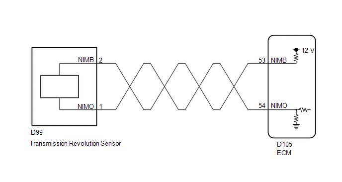
WIRING DIAGRAM
CAUTION / NOTICE / HINT
CAUTION:
-
Strictly observe posted speed limits, traffic laws and road conditions.
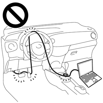
- Do not drive the vehicle with the cable of the GTS contacting the pedals, shift lever or steering wheel.
- Driving the vehicle with the cable of the GTS contacting these areas could impede vehicle control, resulting in a serious accident.
-
Do not operate the GTS while driving the vehicle.
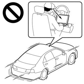
- Operating the GTS while driving the vehicle will prevent you from paying sufficient attention to vehicle surroundings, and could result in a serious accident.
PROCEDURE
| 1. | READ VALUE USING GTS (NIM SENSOR SPEED AND NIM SENSOR VOLTAGE) |
(a) Enter the following menus.
Powertrain > Engine > Data List| Tester Display |
|---|
| NIM Sensor Speed |
| NIM Sensor Voltage |
(b) According to the display on the GTS, read the Data List.
Powertrain > Engine > Data List| Tester Display | Measurement Item | Range | Normal Condition | Diagnostic Note |
|---|---|---|---|---|
| NIM Sensor Speed | Input shaft speed (NIM) | Min.: 0 rpm Max.: 16383 rpm | Input shaft speed (NIM) equal to engine speed (NE): Clutch pedal not depressed, vehicle running | Data is displayed in increments of 50 rpm. |
| NIM Sensor Voltage | Transmission revolution sensor (NIM) output voltage | Min.: 0.000 V Max.: 4.999 V | 0.2 to 1.8 V: Engine idling (Vehicle stopped with shift lever in Neutral) | - |
| Result | Proceed to |
|---|---|
| Data List value is not normal | A |
| Data List value is normal | B |
| B |
 | REPLACE ECM |
|

| 2. | INSPECT TRANSMISSION REVOLUTION SENSOR |
(a) Remove the transmission revolution sensor.
Click here

(b) Connect the auxiliary battery to the transmission revolution sensor as shown in the illustration.
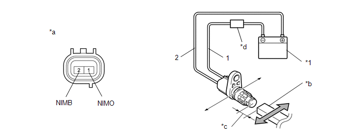
| *1 | Auxiliary Battery | - | - |
| *a | Component without harness connected (Transmission Revolution Sensor) | *b | Magnet |
| *c | 5 mm or less | *d | Ammeter |
(c) Wave a magnetic object left and right 5 mm (0.197 in.) or less from the tip of the transmission revolution sensor to output a high/low signal while measuring the current.
NOTICE:
Make sure to wave the magnetic object during the inspection. The current will not change unless the magnetic object is moved as shown in the illustration.
(d) Measure the current according to the value(s) in the table below.
Standard Current:
| Tester Connection | Condition | Specified Condition |
|---|---|---|
| 1 (NIMO) - 2 (NIMB) | Low signal | 4 to 8 mA |
| 1 (NIMO) - 2 (NIMB) | High signal | 12 to 16 mA |
| NG |
 | REPLACE TRANSMISSION REVOLUTION SENSOR |
|

| 3. | CHECK HARNESS AND CONNECTOR (TRANSMISSION REVOLUTION SENSOR - ECM) |
(a) Disconnect the D99 transmission revolution sensor connector.
(b) Disconnect the D105 ECM connector.
(c) Measure the resistance according to the value(s) in the table below.
Standard Resistance:
| Tester Connection | Condition | Specified Condition |
|---|---|---|
| D99-1 (NIMO) - D105-54 (NIMO) | Always | Below 1 Ω |
| D99-2 (NIMB) - D105-53 (NIMB) | Always | Below 1 Ω |
| D99-1 (NIMO) or D105-54 (NIMO) - Body ground and other terminals | Always | 10 kΩ or higher |
| D99-2 (NIMB) or D105-53 (NIMB) - Body ground and other terminals | Always | 10 kΩ or higher |
(d) Connect the D105 ECM connector.
(e) Connect the D99 transmission revolution sensor connector.
| OK |
 | REPLACE ECM |
| NG |
 | REPAIR OR REPLACE HARNESS OR CONNECTOR (TRANSMISSION REVOLUTION SENSOR - ECM) |
 Transmission Fluid Temperature Sensor "A" Circuit Short to Battery or Open (P071015)
DESCRIPTION Refer to DTC P071015. Click here
DTC No. Detection Item DTC Detection Condition Trouble Area MIL Memory Note P071015 Transmission Fluid Temperature Sensor "A" Circuit Short to Battery or Open Manual transaxle oil temperature sensor (temperature sensor) output voltage exceeds 4...
 Clutch Position Sensor "A"Circuit Short to Battery (P080512,P080514)
DESCRIPTION The clutch pedal stroke sensor assembly is mounted on the clutch pedal, and detects the clutch pedal position and sends signals to the ECM...
Other information:
Toyota Yaris XP210 (2020-2025) Owner's Manual: Child-Restraint System Installation
In this owner’s manual, explanation of child-restraint systems is provided for the following three types of popular child-restraint systems: infant seat, child seat, booster seat. Infant seat An infant seat provides restraint by bracing the infant’s head, neck and back against the seating surface...
Toyota Yaris XP210 (2020-2025) Reapir and Service Manual: Installation
INSTALLATION CAUTION / NOTICE / HINT HINT: Use the same procedure for the RH side and LH side. The following procedure is for the LH side. PROCEDURE 1. INSTALL FRONT DISC BRAKE ANTI-SQUEAL SHIM KIT (a) Install the 2 front disc brake anti-squeal shims to each front disc brake pad...
Categories
- Manuals Home
- Toyota Yaris Owners Manual
- Toyota Yaris Service Manual
- Engine & Hybrid System
- Engine Start Function When Key Battery is Dead
- Diagnostic Trouble Code Chart
- New on site
- Most important about car
Keys

To use the auxiliary key, press the knob and pull out the auxiliary key from the smart key.
