Toyota Yaris: Manual Transaxle System / Pattern Select Switch iMT Mode Circuit
DESCRIPTION
Operating the iMT switch illuminates the iMT indicator light in the combination meter assembly. This displays the iMT system standby condition.
WIRING DIAGRAM
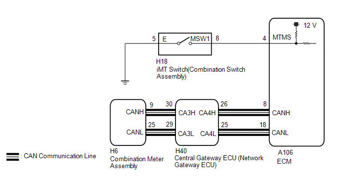
PROCEDURE
| 1. | CHECK DTC OUTPUT (SFI SYSTEM) |
(a) Check for SFI system DTCs.
Click here

| Result | Proceed to |
|---|---|
| DTCs are not output | A |
| DTCs are output | B |
| B |
 | CHECK FOR INTERMITTENT PROBLEMS |
|

| 2. | INSPECT iMT SWITCH (COMBINATION SWITCH ASSEMBLY) |
| (a) Disconnect the H18 iMT Switch (combination switch assembly) connector. |
|
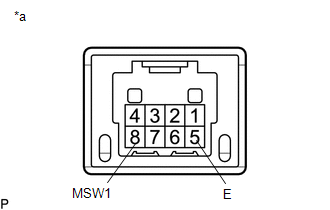
(b) Measure the resistance according to the value(s) in the table below.
Standard Resistance:
| Tester Connection | Condition | Specified Condition |
|---|---|---|
| 8 (MSW1) - 5 (E) | Switch pushed | Below 1 Ω |
| 8 (MSW1) - 5 (E) | Switch not pushed | 10 kΩ or higher |
(c) Connect the H18 iMT Switch (combination switch assembly) connector.
| NG |
 | REPLACE iMT SWITCH (COMBINATION SWITCH ASSEMBLY) |
|

| 3. | CHECK HARNESS AND CONNECTOR (iMT SWITCH (COMBINATION SWITCH ASSEMBLY) - BODY GROUND) |
(a) Disconnect the H18 iMT switch (combination switch assembly) connector.
(b) Measure the resistance according to the value(s) in the table below.
Standard Resistance:
| Tester Connection | Condition | Specified Condition |
|---|---|---|
| H18-5 (E) - Body ground | Always | Below 1 Ω |
(c) Connect the H18 iMT switch (combination switch assembly) connector.
| NG |
 | REPAIR OR REPLACE HARNESS OR CONNECTOR |
|

| 4. | CHECK HARNESS AND CONNECTOR (iMT SWITCH (COMBINATION SWITCH ASSEMBLY) - ECM) |
(a) Disconnect the H18 iMT switch (combination switch assembly) connector.
(b) Disconnect the A106 ECM connector.
(c) Measure the resistance according to the value(s) in the table below.
Standard Resistance:
| Tester Connection | Condition | Specified Condition |
|---|---|---|
| H18-8 (MSW1) -A106-4 (MTMS) | Always | Below 1 Ω |
| H18-8 (MSW1) or A106-4 (MTMS) - Body ground | Always | 10 kΩ or higher |
(d) Connect the A106 ECM connector.
(e) Connect the H18 iMT switch (combination switch assembly) connector.
| OK |
 | REPLACE ECM |
| NG |
 | REPAIR OR REPLACE HARNESS OR CONNECTOR |
 Clutch Position Sensor "A"Circuit Short to Battery (P080512,P080514)
DESCRIPTION The clutch pedal stroke sensor assembly is mounted on the clutch pedal, and detects the clutch pedal position and sends signals to the ECM...

Other information:
Toyota Yaris XP210 (2020-2026) Reapir and Service Manual: Software Incompatibility with Body Control Module Not Programmed (U032251)
DESCRIPTION The forward recognition camera receives vehicle information from the main body ECU (multiplex network body ECU) via CAN communication. DTC U032251 is stored when the forward recognition camera cannot confirm the vehicle information from the main body ECU (multiplex network body ECU)...
Toyota Yaris XP210 (2020-2026) Reapir and Service Manual: IG Circuit Short to Ground (B227111)
DESCRIPTION This DTC is stored when a malfunction in the IG circuit or IG hold circuit of the certification ECU (smart key ECU assembly) is detected. DTC No. Detection Item DTC Detection Condition Trouble Area Note B227111 IG Circuit Short to Ground When either of the following conditions is met (1-trip detection logic*1): The IG circuit of the certification ECU (smart key ECU assembly) is malfunctioning...
Categories
- Manuals Home
- Toyota Yaris Owners Manual
- Toyota Yaris Service Manual
- Adjustment
- Key Battery Replacement
- Headlights
- New on site
- Most important about car
Refueling
Before refueling, close all the doors, windows, and the liftgate/trunk lid, and switch the ignition OFF.
To open the fuel-filler lid, pull the remote fuel-filler lid release.
