Toyota Yaris: Lighting System / Hazard Warning Switch Circuit
DESCRIPTION
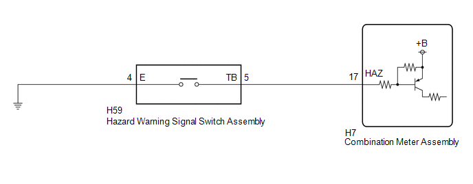
The combination meter assembly receives the hazard warning signal switch assembly on signal and controls the operation of the hazard warning lights.
WIRING DIAGRAM
CAUTION / NOTICE / HINT
NOTICE:
When replacing the combination meter assembly, always replace it with a new one. If a combination meter assembly which was installed to another vehicle is used, the information stored in it will not match the information from the vehicle and a DTC may be stored.
PROCEDURE
| 1. | READ VALUE USING GTS |
(a) Enter the following menus: Body Electrical / Combination Meter / Data List.
(b) Read the Data List according to the display on the GTS.
Body Electrical > Combination Meter > Data List| Tester Display | Measurement Item | Range | Normal Condition | Diagnostic Note |
|---|---|---|---|---|
| Hazard Flasher Switch | Hazard warning signal switch signal | OFF or ON | OFF: Hazard warning signal switch off ON: Hazard warning signal switch on | - |
| Tester Display |
|---|
| Hazard Flasher Switch |
OK:
Normal conditions listed above are displayed.
| OK |
.gif) | PROCEED TO NEXT SUSPECTED AREA SHOWN IN PROBLEM SYMPTOMS TABLE |
|
.gif)
| 2. | INSPECT HAZARD WARNING SIGNAL SWITCH ASSEMBLY |
Click here
.gif)
| NG |
| REPLACE HAZARD WARNING SIGNAL SWITCH ASSEMBLY |
|
| 3. | CHECK HARNESS AND CONNECTOR (HAZARD WARNING SIGNAL SWITCH ASSEMBLY - COMBINATION METER ASSEMBLY AND BODY GROUND) |
(a) Disconnect the H7 combination meter assembly connector.
(b) Measure the resistance according to the value(s) in the table below.
Standard Resistance:
| Tester Connection | Condition | Specified Condition |
|---|---|---|
| H59-5 (TB) - H7-17 (HAZ) | Always | Below 1 Ω |
| H59-5 (TB) or H7-17 (HAZ) - Body ground | Always | 10 kΩ or higher |
| H59-4 (E) - Body ground | Always | Below 1 Ω |
| OK |
| REPLACE COMBINATION METER ASSEMBLY |
| NG |
| REPAIR OR REPLACE HARNESS OR CONNECTOR |
 Rear Fog Light Circuit
DESCRIPTION The main body ECU (multiplex network body ECU) controls the rear fog light. WIRING DIAGRAM
CAUTION / NOTICE / HINT NOTICE:
Before replacing the main body ECU (multiplex network body ECU), refer to Registration...
 LO-beam Headlight does not Illuminate
DESCRIPTION The main body ECU (multiplex network body ECU) controls the low beam headlights. WIRING DIAGRAM
CAUTION / NOTICE / HINT NOTICE:
Before replacing the main body ECU (multiplex network body ECU), refer to Registration...
Other information:
Toyota Yaris XP210 (2020-2026) Owner's Manual: Key Battery Replacement
If the buttons on the smart key are inoperable and the operation indicator light does not flash, the battery may be dead. Replace with a new battery before the smart key becomes unusable. The following conditions indicate that the battery power is low: The KEY indicator light (green) flashes in the combination meter for about 30 seconds after the engine is switched OFF...
Toyota Yaris XP210 (2020-2026) Owner's Manual: Dashboard Precautions
Prevent caustic solutions such as perfume and cosmetic oils from contacting the dashboard. They will damage and discolor the dashboard. If these solutions get on the dashboard, wipe them off immediately. Instrument panel top When cleaning, it is recommended that you use a clean towel dampened in a mild detergent to remove soiling...
Categories
- Manuals Home
- Toyota Yaris Owners Manual
- Toyota Yaris Service Manual
- Key Battery Replacement
- How to use USB mode
- Diagnostic Trouble Code Chart
- New on site
- Most important about car
Break-In Period
No special break-in is necessary, but a few precautions in the first 600 miles (1,000 km) may add to the performance, economy, and life of the vehicle.
Do not race the engine. Do not maintain one constant speed, either slow or fast, for a long period of time. Do not drive constantly at full-throttle or high engine rpm for extended periods of time. Avoid unnecessary hard stops. Avoid full-throttle starts.