Toyota Yaris: Lighting System / LO-beam Headlight does not Illuminate
DESCRIPTION
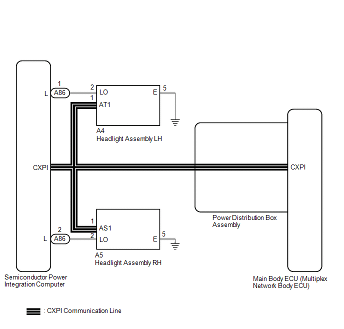
The main body ECU (multiplex network body ECU) controls the low beam headlights.
WIRING DIAGRAM
CAUTION / NOTICE / HINT
NOTICE:
-
Before replacing the main body ECU (multiplex network body ECU), refer to Registration.
Click here
.gif)
-
First perform the communication function inspections in How to Proceed with Troubleshooting to confirm that there are no CAN communication malfunctions before troubleshooting this symptom.
Click here
-
First perform the communication function inspections in How to Proceed with Troubleshooting to confirm that there are no CXPI communication malfunctions before troubleshooting this symptom.
Click here
PROCEDURE
| 1. | PERFORM ACTIVE TEST USING GTS |
(a) Perform the Active Test according to the display on the GTS.
Body Electrical > Main Body > Active Test| Tester Display | Measurement Item | Control Range | Diagnostic Note |
|---|---|---|---|
| Low Beam Headlight | Low beam headlights | OFF or ON | - |
| Tester Display |
|---|
| Low Beam Headlight |
OK:
Low beam headlights illuminate.
| Result | Proceed to |
|---|---|
| OK | A |
| NG (LH side low beam light does not illuminate.) | B |
| NG (RH side low beam light does not illuminate.) | C |
| A |
.gif) | PROCEED TO NEXT SUSPECTED AREA SHOWN IN PROBLEM SYMPTOMS TABLE |
| C |
| GO TO STEP 7 |
|
.gif)
| 2. | INSPECT HEADLIGHT ASSEMBLY LH (LO TERMINAL VOLTAGE) |
(a) Disconnect the A4 headlight assembly LH connector.
(b) Measure the voltage according to the value(s) in the table below.
Standard Voltage:
| Tester Connection | Condition | Specified Condition |
|---|---|---|
| A4-2 (LO) - Body ground | Light control switch in head position | 11 to 14 V |
| NG |
| REPAIR OR REPLACE HARNESS OR CONNECTOR |
|
| 3. | CHECK HARNESS AND CONNECTOR (HEADLIGHT ASSEMBLY LH - BODY GROUND) |
(a) Measure the resistance according to the value(s) in the table below.
Standard Resistance:
| Tester Connection | Condition | Specified Condition |
|---|---|---|
| A4-5 (E) - Body ground | Always | Below 1 Ω |
| NG |
| REPAIR OR REPLACE HARNESS OR CONNECTOR |
|
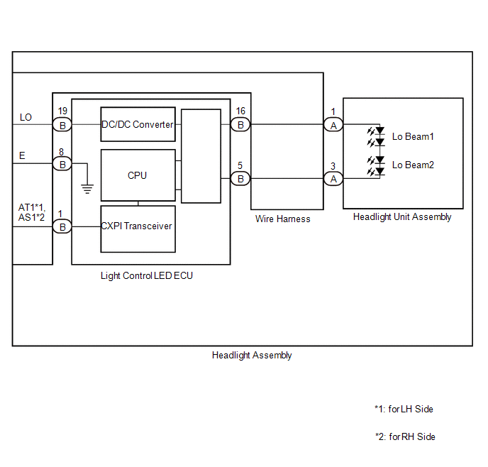
| 4. | CHECK HARNESS AND CONNECTOR (HEADLIGHT UNIT ASSEMBLY LH - LIGHT CONTROL ECU LH) |
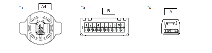
| *a | Component without harness connected (to Wire Harness) | *b | Component without harness connected (to Light Control LED ECU) |
| *c | Component without harness connected (to Headlight Unit Assembly) | - | - |
(a) Remove the headlight assembly LH.
Click here
(b) Remove the Wire Harness.
Click here
(c) Measure the resistance according to the value(s) in the table below.
Standard Resistance:
| Tester Connection | Condition | Specified Condition |
|---|---|---|
| A-[1] - B-[16] | Always | Below 1 Ω |
| A-[3] - B-[5] | Always | Below 1 Ω |
| A4-2 (LO) - B-[19] | Always | Below 1 Ω |
| A4-5 (E) - B-[8] | Always | Below 1 Ω |
| NG |
| REPLACE HARNESS OR CONNECTOR |
|
| 5. | INSPECT LIGHT CONTROL LED ECU LH |
(a) Interchange the light control LED ECU LH with RH and connect the connectors to them.
|
| 6. | CHECK OPERATION (LOW BEAM HEADLIGHT) |
(a) Check that the low beam headlight operates normally.
OK:
Low beam headlight operates normally.
| OK |
| REPLACE LIGHT CONTROL LED ECU LH |
| NG |
| REPLACE HEADLAMP UNIT ASSEMBLY LH |
| 7. | INSPECT HEADLIGHT ASSEMBLY RH (LO TERMINAL VOLTAGE) |
(a) Disconnect the A5 headlight assembly RH connector.
(b) Measure the voltage according to the value(s) in the table below.
Standard Voltage:
| Tester Connection | Condition | Specified Condition |
|---|---|---|
| A5-2 (LO) - Body ground | Light control switch in head position | 11 to 14 V |
| NG |
| REPAIR OR REPLACE HARNESS OR CONNECTOR |
|
| 8. | CHECK HARNESS AND CONNECTOR (HEADLIGHT ASSEMBLY RH - BODY GROUND) |
(a) Measure the resistance according to the value(s) in the table below.
Standard Resistance:
| Tester Connection | Condition | Specified Condition |
|---|---|---|
| A5-5 (E) - Body ground | Always | Below 1 Ω |
| NG |
| REPAIR OR REPLACE HARNESS OR CONNECTOR |
|
| 9. | CHECK HARNESS AND CONNECTOR (HEADLIGHT UNIT ASSEMBLY RH - LIGHT CONTROL ECU RH) |

| *a | Component without harness connected (to Wire Harness) | *b | Component without harness connected (to Light Control LED ECU) |
| *c | Component without harness connected (to Headlight Unit Assembly) | - | - |
(a) Remove the headlight assembly RH.
Click here
(b) Remove the Wire Harness.
Click here
(c) Measure the resistance according to the value(s) in the table below.
Standard Resistance:
| Tester Connection | Condition | Specified Condition |
|---|---|---|
| A-[1] - B-[16] | Always | Below 1 Ω |
| A-[3] - B-[5] | Always | Below 1 Ω |
| A5-2 (LO) - B-[19] | Always | Below 1 Ω |
| A5-5 (E) - B-[8] | Always | Below 1 Ω |
| NG |
| REPLACE HARNESS OR CONNECTOR |
|
| 10. | INSPECT LIGHT CONTROL LED ECU RH |
(a) Interchange the light control LED ECU RH with LH and connect the connectors to them.
Click here
|
| 11. | CHECK OPERATION (LOW BEAM HEADLIGHT) |
(a) Check that the low beam headlight operates normally.
OK:
Low beam headlight operates normally.
| OK |
| REPLACE LIGHT CONTROL LED ECU RH |
| NG |
| REPLACE HEADLIGHT UNIT ASSEMBLY RH |
 Hazard Warning Switch Circuit
DESCRIPTION The combination meter assembly receives the hazard warning signal switch assembly on signal and controls the operation of the hazard warning lights...
 Parking Brake Switch Circuit
DESCRIPTION The main body ECU (multiplex network body ECU) detects the condition of the parking brake switch assembly. WIRING DIAGRAM
CAUTION / NOTICE / HINT NOTICE: Before replacing the main body ECU (multiplex network body ECU), refer to Registration...
Other information:
Toyota Yaris XP210 (2020-2026) Reapir and Service Manual: Installation
I..
Toyota Yaris XP210 (2020-2026) Reapir and Service Manual: Engine Hood Courtesy Switch
ComponentsCOMPONENTS ILLUSTRATION *1 ENGINE HOOD COURTESY SWITCH (HOOD LOCK ASSEMBLY) - - N*m (kgf*cm, ft.*lbf): Specified torque MP grease RemovalREMOVAL PROCEDURE 1. REMOVE ENGINE HOOD COURTESY SWITCH (HOOD LOCK ASSEMBLY) (a) Disconnect the connector...
Categories
- Manuals Home
- Toyota Yaris Owners Manual
- Toyota Yaris Service Manual
- Opening and Closing the Liftgate/Trunk Lid
- Adjustment
- Brake System Control Module "A" System Voltage System Voltage Low (C137BA2)
- New on site
- Most important about car
Supplemental Restraint System (SRS) Precautions
The front and side supplemental restraint systems (SRS) include different types of air bags. Please verify the different types of air bags which are equipped on your vehicle by locating the “SRS AIRBAG” location indicators. These indicators are visible in the area where the air bags are installed.
The air bags are installed in the following locations:
The steering wheel hub (driver air bag) The front passenger dashboard (front passenger air bag) The outboard sides of the front seatbacks (side air bags) The front and rear window pillars, and the roof edge along both sides (curtain air bags)