Toyota Yaris: Condenser / Reassembly
REASSEMBLY
PROCEDURE
1. INSTALL COOLER DRYER
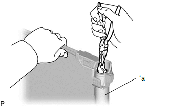
| (a) Using pliers, install a new cooler dryer to the modulator. |
|
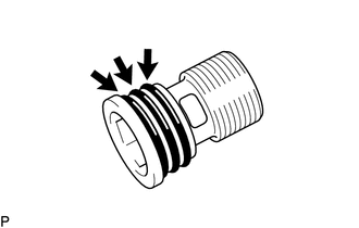
| (b) Sufficiently apply compressor oil to the 3 O-rings and fitting surfaces of a new cap. Compressor Oil: ND-OIL 8 or equivalent NOTICE: Keep the O-rings and O-ring fitting surfaces free from dirt or foreign matter. |
|
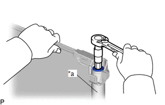
| (c) Using a 14 mm straight hexagon, install the cap to the modulator. Torque: 4.0 N·m {41 kgf·cm, 35 in·lbf} |
|
 Disassembly
DISASSEMBLY PROCEDURE 1. REMOVE COOLER DRYER (a) Using a 14 mm straight hexagon, remove the cap from the modulator.
*a Modulator (b) Using needle-nose pliers, remove the cooler dryer from the modulator...
 Installation
INSTALLATION PROCEDURE 1. INSTALL COOLER CONDENSER ASSEMBLY (a) Engage the guide to install the cooler condenser assembly. NOTICE: Do not damage the cooler condenser assembly or radiator assembly when installing the cooler condenser assembly...
Other information:
Toyota Yaris XP210 (2020-2026) Reapir and Service Manual: Utility
UTILITY REFRIGERANT SHORTAGE CHECK USING GTS (a) Check that the following conditions are met and perform the refrigerant shortage check according to the display on the GTS. Measurement Condition: Item Condition A/C switch On Ambient temperature*1 0 to 49°C (32 to 120°F) Blower speed HI *1: If the ambient temperature is not within the range shown, do not perform this check...
Toyota Yaris XP210 (2020-2026) Reapir and Service Manual: Parts Location
P..
Categories
- Manuals Home
- Toyota Yaris Owners Manual
- Toyota Yaris Service Manual
- Key Battery Replacement
- Auto Lock/Unlock Function
- G16e-gts (engine Mechanical)
- New on site
- Most important about car
Supplemental Restraint System (SRS) Precautions
The front and side supplemental restraint systems (SRS) include different types of air bags. Please verify the different types of air bags which are equipped on your vehicle by locating the “SRS AIRBAG” location indicators. These indicators are visible in the area where the air bags are installed.
The air bags are installed in the following locations:
The steering wheel hub (driver air bag) The front passenger dashboard (front passenger air bag) The outboard sides of the front seatbacks (side air bags) The front and rear window pillars, and the roof edge along both sides (curtain air bags)