Toyota Yaris: Air Conditioning Unit / Reassembly
REASSEMBLY
PROCEDURE
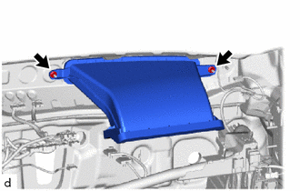
1. INSTALL AIR DUCT ASSEMBLY
| (a) Install the air duct assembly with the 2 nuts. |
|
| (b) Install the front panel silencer as shown in the illustration. |
|
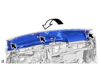
(c) Install the 3 retainers.
2. INSTALL NO. 1 COOLER THERMISTOR
Click here

3. INSTALL NO. 1 COOLER EVAPORATOR SUB-ASSEMBLY
| (a) Install the No. 1 cooler evaporator sub-assembly with No. 1 cooler thermistor to the upper heater case. |
|
| (b) Engage the guides and claws to install the upper heater case with No. 1 cooler evaporator sub-assembly. |
|
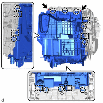
(c) Install the 2 screws.
| (d) Engage the guides and clamp. |
|
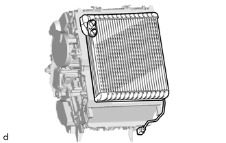
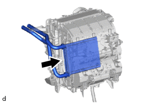
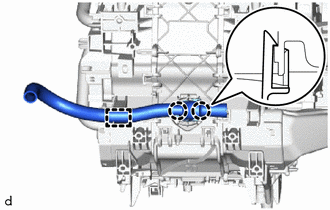
4. INSTALL HEATER RADIATOR UNIT SUB-ASSEMBLY
| (a) Install the heater radiator unit sub-assembly as shown in the illustration. |
|
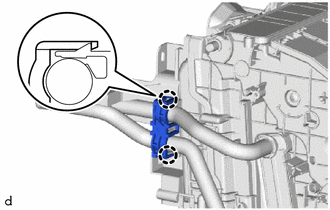
5. INSTALL HEATER CLAMP
| (a) Engage the claws to install the heater clamp. |
|
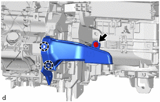
6. INSTALL HEATER COVER
| (a) Install the heater cover with the screw. |
|
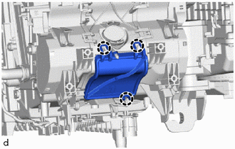
7. INSTALL NO. 1 AIR CONDITIONING RADIATOR DAMPER SERVO SUB-ASSEMBLY
(a) Move the gear of the air conditioner radiator assembly so that the shape of the center gear portion of the air conditioner radiator assembly is aligned with the sensor shaft and output shaft of the No. 1 air conditioning radiator damper servo sub-assembly, and temporarily install the No. 1 air conditioning radiator damper servo sub-assembly as shown in the illustration.
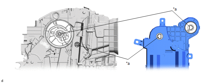
| *a | Align shapes | - | - |
| (b) Install the No. 1 air conditioning radiator damper servo sub-assembly with the 3 screws. |
|
8. INSTALL BLOWER ASSEMBLY
Click here

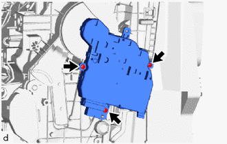
9. INSTALL AIR CONDITIONING AMPLIFIER ASSEMBLY
| (a) Engage the guide to install the air conditioning amplifier assembly. |
|
(b) Install the 2 screws.
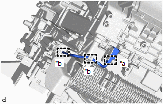
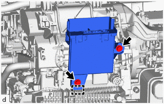
10. INSTALL AIR CONDITIONING HARNESS ASSEMBLY
| (a) Engage the guides. |
|
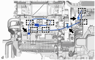
(b) Connect 3 connectors to install the air conditioning harness assembly.
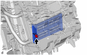
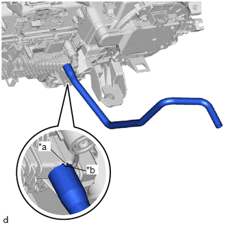
11. INSTALL DRAIN COOLER HOSE
| (a) Align the hose notch with the rib as shown in the illustration and install the drain cooler hose. |
|
12. INSTALL COVER
| (a) Engage the claws to install the cover. |
|
13. INSTALL NO. 2 AIR DUCT
| (a) Engage the claws to install the No. 2 air duct. |
|
(b) Install the screw.
14. INSTALL ASPIRATOR
| (a) Engage the claws and guide to install the aspirator. |
|
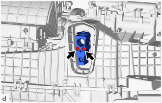
15. INSTALL COOLER EXPANSION VALVE
(a) Sufficiently apply compressor oil to 2 new O-rings and the fitting surfaces of the No. 1 cooler evaporator sub-assembly.
Compressor Oil:
ND-OIL 8 or equivalent
(b) Install the 2 O-rings to the No. 1 cooler evaporator sub-assembly.
NOTICE:
Keep the O-rings and O-ring fitting surfaces free of foreign matter.
| (c) Using a 4 mm hexagon socket wrench, install the cooler expansion valve with the 2 hexagon bolts. Torque: 3.5 N·m {36 kgf·cm, 31 in·lbf} |
|
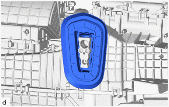
16. INSTALL COOLER PIPE GROMMET
| (a) Install the cooler pipe grommet. |
|
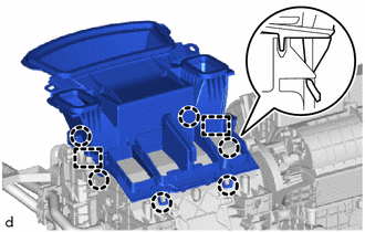
17. INSTALL LOWER DEFROSTER NOZZLE ASSEMBLY
| (a) Engage the guides and claws to install the lower defroster nozzle assembly. |
|
 Disassembly
DISASSEMBLY PROCEDURE 1. REMOVE LOWER DEFROSTER NOZZLE ASSEMBLY (a) Disengage the claws and guides to remove the lower defroster nozzle assembly.
2...
 Installation
INSTALLATION PROCEDURE 1. TEMPORARILY INSTALL AIR CONDITIONER UNIT ASSEMBLY (a) Temporarily install the air conditioner unit assembly to the instrument panel reinforcement assembly with the 3 bolts...
Other information:
Toyota Yaris XP210 (2020-2026) Reapir and Service Manual: Diagnosis System
DIAGNOSIS SYSTEM DIAGNOSIS MODE FUNCTION (a) When a malfunction occurs in the lane tracing assist system, the LTA indicator light illuminates in yellow and a message is displayed on the multi-information display. Warning Message Details DTC/RoB LTA Indicator "LTA Malfunction Visit Your Dealer" Lane tracing assist system malfunction is detected Stored Illuminated in yellow "LTA Unavailable" Sensor other than the forward recognition camera sensor is temporary unavailable Stored Illuminated in yellow LTA Indicator Status Chart LTA Indicator Status Status *: When entering the lane departure warning under the lane departure restraint, changes to yellow blinking...
Toyota Yaris XP210 (2020-2026) Reapir and Service Manual: Barometric Pressure - Turbocharger / Supercharger Boost Sensor "A" Signal Compare Failure (P00CF62)
DESCRIPTION At ignition switch to ON or during idling, the No. 2 turbo pressure sensor and the atmospheric pressure sensor built into the ECM are at atmospheric pressure and their outputs match. DTC No. Detection Item DTC Detection Condition Trouble Area MIL Note P00CF62 Barometric Pressure - Turbocharger / Supercharger Boost Sensor "A" Signal Compare Failure 15 kPa [2...
Categories
- Manuals Home
- Toyota Yaris Owners Manual
- Toyota Yaris Service Manual
- How to connect USB port/Auxiliary jack
- Brake System Control Module "A" System Voltage System Voltage Low (C137BA2)
- Opening and Closing the Liftgate/Trunk Lid
- New on site
- Most important about car
Front Seat Belt Pretensioners
The front seat belt pretensioners are designed to deploy in moderate or severe frontal, near frontal collisions.
In addition, the pretensioners operate when a side collision or a rollover accident is detected. The pretensioners operate differently depending on what types of air bags are equipped. For more details about the seat belt pretensioner operation, refer to the SRS Air Bag Deployment Criteria.