Toyota Yaris: Air Conditioning Unit / Installation
INSTALLATION
PROCEDURE
1. TEMPORARILY INSTALL AIR CONDITIONER UNIT ASSEMBLY
(a) Temporarily install the air conditioner unit assembly to the instrument panel reinforcement assembly with the 3 bolts.
2. INSTALL INSTRUMENT PANEL REINFORCEMENT ASSEMBLY WITH AIR CONDITIONER UNIT ASSEMBLY
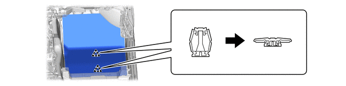
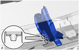
(a) Engage the clamps.
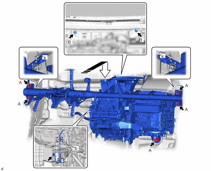
| *a | Guide | *b | Clamp |
 | Install in this Direction | - | - |
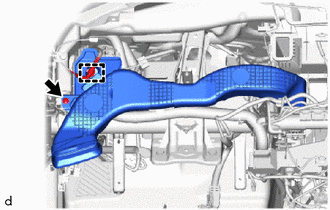
(b) Connect the connector.
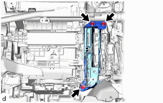
(c) Engage the guides to install the instrument panel reinforcement assembly with air conditioner unit assembly as shown in the illustration.
(d) Install the 6 bolts.
Torque:
Bolt A :
31 N·m {316 kgf·cm, 23 ft·lbf}
Bolt B :
25 N·m {255 kgf·cm, 18 ft·lbf}
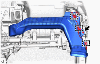
(e) Temporarily install the nut.
NOTICE:
Do not fully tighten the nut.
3. INSTALL NO. 1 INSTRUMENT PANEL BRACE SUB-ASSEMBLY
(a) Install the No. 1 instrument panel brace sub-assembly with the bolt and nut.
Torque:
Bolt :
20 N·m {204 kgf·cm, 15 ft·lbf}
Nut :
18 N·m {184 kgf·cm, 13 ft·lbf}
(b) Temporarily install the screw.
NOTICE:
Do not fully tighten the screw.
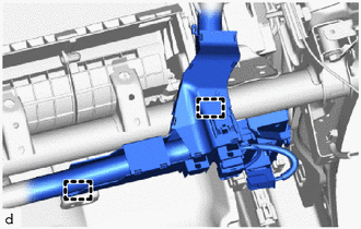
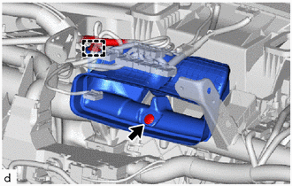
4. INSTALL AIR CONDITIONER UNIT ASSEMBLY
(a) Tighten the 3 bolts, screws and nut in the order shown in the illustration to install the air conditioner unit assembly.
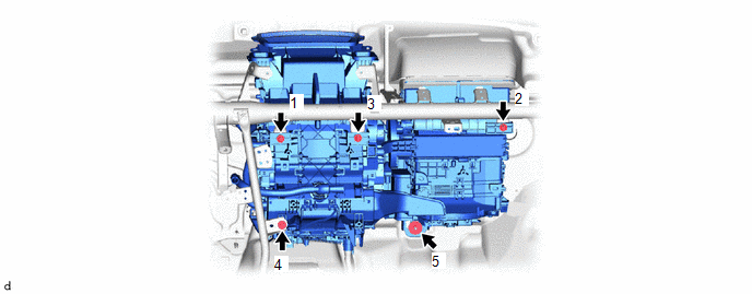
Torque:
Bolt :
9.5 N·m {97 kgf·cm, 84 in·lbf}
Nut :
6.0 N·m {61 kgf·cm, 53 in·lbf}
5. INSTALL INSTRUMENT PANEL WIRE
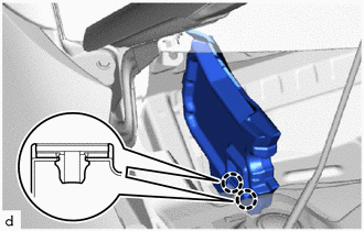
(a) Engage the clamps to install the instrument panel wire.
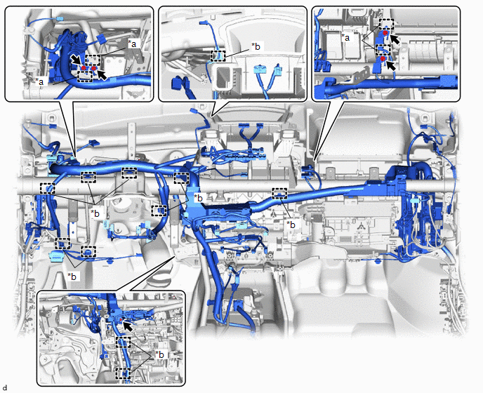
| *a | Guide | *b | Clamp |
(b) Connect the each connector.
(c) Connect the instrument panel wire with the bolt.
Torque:
10 N·m {102 kgf·cm, 7 ft·lbf}
(d) Engage the guides to connect the 4 ground wires.
(e) Install the 4 ground wires with the 4 bolts.
Torque:
10 N·m {102 kgf·cm, 7 ft·lbf}
| (f) Engage the clamp. |
|
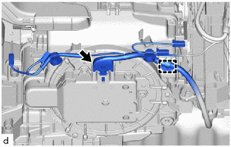
(g) Connect the connector.
| (h) Install the ECU integration box RH with the 2 nuts and bolt. Torque: 8.0 N·m {82 kgf·cm, 71 in·lbf} |
|
| (i) Engage the clamps. |
|
6. INSTALL POWER DISTRIBUTION BOX ASSEMBLY WITH MULTIPLEX NETWORK BODY ECU
Click here

7. INSTALL NO. 3 INSTRUMENT PANEL TO COWL BRACE SUB-ASSEMBLY
Click here

8. INSTALL METER MIRROR SUB-ASSEMBLY (w/ Headup Display)
Click here

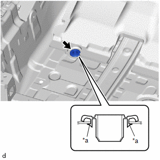
9. INSTALL COOLER UNIT DRAIN HOSE GROMMET
| (a) Install a new cooler unit drain hose grommet. NOTICE:
|
|
10. CONNECT DRAIN COOLER HOSE
| (a) Connect the drain cooler hose. |
|
11. INSTALL NO. 4 DASH PANEL INSULATOR PAD
(a) Engage the 2 clips to install the No. 4 dash panel insulator pad.
12. INSTALL FRONT FLOOR CARPET ASSEMBLY
(a) Install the front floor carpet assembly with the 2 clips as shown in the illustration.

13. INSTALL FRONT SEAT ASSEMBLY LH
Click here

14. INSTALL FRONT SEAT ASSEMBLY RH
HINT:
Use the same procedure as for the LH side.
15. INSTALL NO. 1 HEATER TO REGISTER DUCT SUB-ASSEMBLY
| (a) Engage the clamp to install the No. 1 heater to register duct sub-assembly. |
|
(b) Install the clip.
16. INSTALL NO. 2 HEATER TO REGISTER DUCT SUB-ASSEMBLY
| (a) Engage the clamps to install the No. 2 heater to register duct sub-assembly. |
|
(b) Install the clip.
17. INSTALL CENTER HEATER TO REGISTER DUCT SUB-ASSEMBLY
| (a) Engage the clamp to install the center heater to register duct sub-assembly. |
|
(b) Install the clip.
18. INSTALL STEERING COLUMN ASSEMBLY
Click here

19. INSTALL NO. 1 AIR DUCT
| (a) Engage the claws and clamps to install the No. 1 air duct. |
|
(b) Install the 2 bolts.
20. INSTALL INSTRUMENT PANEL ASSEMBLY
Click here

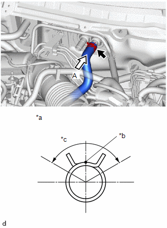
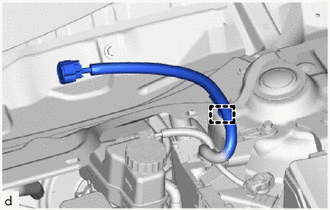
21. CONNECT INLET HEATER WATER HOSE
| (a) Connect the inlet heater water hose with the marking (white) facing up and engage the clip within the area shown in the illustration. NOTICE: Do not apply excessive force to the inlet heater water hose. |
|
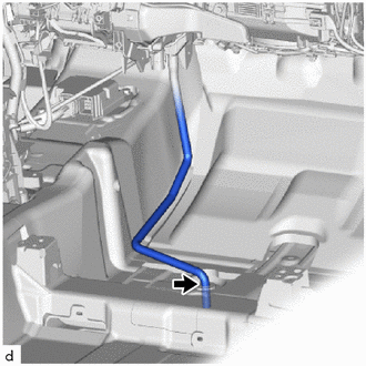
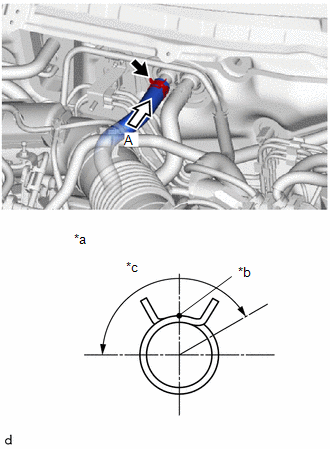
22. CONNECT OUTLET HEATER WATER HOSE
| (a) Connect the outlet heater water hose with the marking (green) facing up and engage the clip within the area shown in the illustration. NOTICE: Do not apply excessive force to the outlet heater water hose. |
|
23. INSTALL AIR CONDITIONING TUBE AND ACCESSORY ASSEMBLY
(a) Remove the vinyl tape from the air conditioning tube and accessory assembly.
(b) Apply sufficient compressor oil to 2 new O-rings and fitting surface of the air conditioning tube and accessory assembly.
Compressor Oil:
ND-OIL 8 or equivalent
(c) Install the 2 O-rings to the air conditioning tube and accessory assembly.
NOTICE:
Keep the O-ring and O-ring fitting surface free of foreign matter.
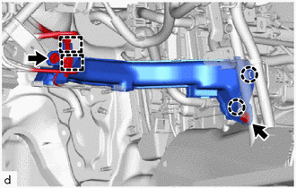
(d) Connect the air conditioning tube and accessory assembly.
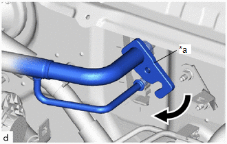
| (e) Rotate the hook connector as shown in the illustration. |
|
(f) Insert the hose joint into the fitting hole securely and install the bolt.
Torque:
9.5 N·m {97 kgf·cm, 84 in·lbf}
24. INSTALL DASH PANEL HEAT INSULATOR
Click here

25. INSTALL OUTER COWL TOP PANEL SUB-ASSEMBLY
(a) Install the outer cowl top panel sub-assembly with the 11 bolts.
Torque:
12 N·m {122 kgf·cm, 9 ft·lbf}
| (b) Engage the clamp. |
|
26. INSTALL NO. 1 FRONT VENTILATOR SEAL
| (a) Engage the claws to install the No. 1 front ventilator seal. |
|
27. INSTALL WATER GUARD PLATE RH
| (a) Engage the claws to install the water guard plate RH. |
|
28. INSTALL WINDSHIELD WIPER MOTOR AND LINK
Click here

29. ADD ENGINE COOLANT
Click here

30. CHARGE AIR CONDITIONING SYSTEM WITH REFRIGERANT
Click here

31. INSPECT FOR COOLANT LEAK
Click here

32. WARM UP ENGINE
Click here

33. INSPECT FOR REFRIGERANT LEAK
Click here

34. INSTALL NO. 1 ENGINE UNDER COVER ASSEMBLY
Click here

35. INITIALIZATION SERVO MOTOR
Click here

36. PERFORM REGISTRATION
Click here

 Reassembly
REASSEMBLY PROCEDURE 1. INSTALL AIR DUCT ASSEMBLY (a) Install the air duct assembly with the 2 nuts.
(b) Install the front panel silencer as shown in the illustration...
 Ambient Temperature Sensor
ComponentsCOMPONENTS ILLUSTRATION
*1 THERMISTOR ASSEMBLY - - RemovalREMOVAL PROCEDURE 1. REMOVE FRONT BUMPER ASSEMBLY Click here
2. REMOVE THERMISTOR ASSEMBLY (a) Disengage the clamp...
Other information:
Toyota Yaris XP210 (2020-2026) Reapir and Service Manual: Installation
INSTALLATION PROCEDURE 1. INSTALL REAR DIFFERENTIAL SUPPORT (a) Install the differential support to the rear differential carrier assembly with 3 new bolts. Torque: 120 N·m {1224 kgf·cm, 89 ft·lbf} 2. INSTALL REAR DIFFERENTIAL DYNAMIC DAMPER (a) Install the rear differential dynamic damper to the differential support with 2 bolts...
Toyota Yaris XP210 (2020-2026) Owner's Manual: Keyless Entry System
This system uses the key buttons to remotely lock and unlock the doors and the liftgate, and opens the trunk lid. The system can start the engine without having to take the key out of your purse or pocket. It can also help you signal for attention...
Categories
- Manuals Home
- Toyota Yaris Owners Manual
- Toyota Yaris Service Manual
- Fuel Gauge
- Key Battery Replacement
- Diagnostic Trouble Code Chart
- New on site
- Most important about car
Keys

To use the auxiliary key, press the knob and pull out the auxiliary key from the smart key.
