Toyota Yaris: Headlight Assembly / Reassembly
REASSEMBLY
CAUTION / NOTICE / HINT
NOTICE:
- Handle components indoors as much as possible to prevent foreign matter from entering and adhering to headlight assembly components.
- Do not reuse parts which have reduced fastening ability due to thread damage.
- When installing components, make sure that the wire harness is not pinched or pulled.
- Do not use solvent to clean components. Only clean them with a dry cloth.
HINT:
- Use the same procedure for the RH side and LH side.
- The following procedure is for the LH side.
PROCEDURE
1. INSTALL HEADLIGHT HOUSING SUB-ASSEMBLY
HINT:
As the headlight housing sub-assembly is available as a supply part, proceed to the next step if it is necessary to change the headlight housing sub-assembly.
| (a) Install the pivot screw. |
|
| (b) Engage the claws to install a new aiming screw. |
|
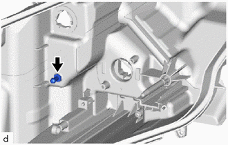
2. INSTALL HEADLIGHT CORD
(a) Engage the claws to install the headlight cord.
.png) | Install in this Direction |
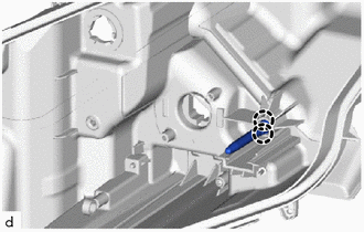
(b) Engage the clamp.
3. INSTALL HEADLIGHT UNIT ASSEMBLY
NOTICE:
- Make sure to wear clean rubber gloves when performing this procedure.
- Do not allow dirt or foreign matter to get on the headlight unit assembly or other components.
- Prevention of static electricity is required during this procedure.
- Use static electricity countermeasures SST (desktop anti-static mat set) and observe all precautions to prevent damage to the system by electrostatic discharge (ESD).
- Do not touch the headlight unit assembly with bare hands.
- Do not allow metallic surfaces to become dirty, as such surfaces become damaged even if they are only lightly wiped with a soft cloth.
- If there are any fingerprints or foreign matter on the headlight unit assembly or other components, wipe them off with a soft cloth.
- Do not use solvent to clean components. Only clean them with a dry cloth.
SST: 09890-47010
09891-04010
09891-04020
09891-04030
09891-04040
(a) When reusing the headlight unit assembly:
| (1) Engage the claws to install a new pivot collar. |
|
(b) Temporarily install the headlight unit assembly to the headlight housing sub-assembly.
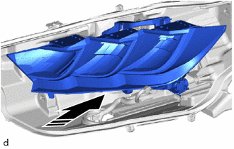
|
| Install in this Direction |
| (c) While holding the headlight unit assembly by hand, turn the aiming screw. HINT: Turn the aiming screw the same number of times as they were turned during removal. |
|
| (d) Engage the pivot collar. |
|
(e) Connect the connector.
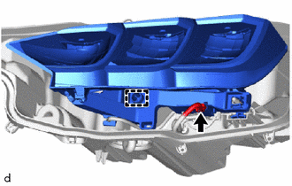
4. INSTALL LIGHT CONTROL LED ECU
NOTICE:
- Make sure to wear clean rubber gloves when performing this procedure.
- Do not allow dirt or foreign matter to get on the headlight unit assembly or other components.
- Prevention of static electricity is required during this procedure.
- Use static electricity countermeasures SST (desktop anti-static mat set) and observe all precautions to prevent damage to the system by electrostatic discharge (ESD).
- Do not touch the headlight unit assembly with bare hands.
- Do not allow metallic surfaces to become dirty, as such surfaces become damaged even if they are only lightly wiped with a soft cloth.
- If there are any fingerprints or foreign matter on the headlight unit assembly or other components, wipe them off with a soft cloth.
- Do not use solvent to clean components. Only clean them with a dry cloth.
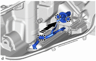
| (a) Engage the guide to install the light control LED ECU. |
|
.png)
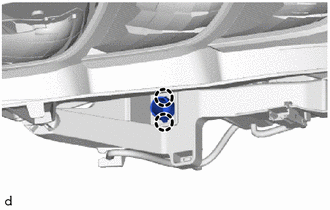
(b) Install the screw.
| (c) Connect the connector. |
|
.png)
5. INSTALL HEADLIGHT LENS GASKET
NOTICE:
- The headlight lens gasket must not be reused.
- Make sure to wear clean rubber gloves when performing this procedure.
- Do not touch the inner surface of the lens and metallic surfaces as much as possible, or they may become dirty.
- Do not allow metallic surfaces to become dirty, as such surfaces become damaged even if they are only lightly wiped with a soft cloth.
- If there are any fingerprints or foreign matter on the headlight unit assembly or other components, wipe them off with a soft cloth.
- Do not use solvent to clean components. Only clean them with a dry cloth.
(a) Completely remove the old headlight lens gasket.
(b) Clean the installation groove of the headlight lens sub-assembly.
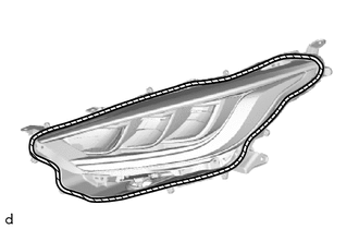
.png) | Cleaning Area |
| (c) Partially remove the release paper from a new headlight lens gasket, and cut off a piece of it. |
|
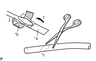
(d) Fold the release paper over the tip of a screwdriver and secure it in place with tape as indicated by the arrows, in the order shown in the illustration.
(e) Using scissors, cut the end of the headlight lens gasket at a 45° angle.
| (f) Install the headlight lens gasket as shown in the illustration. |
|
(g) Using a screwdriver with their tips wrapped in release paper, completely press the headlight lens gasket into the groove to install it.
6. INSTALL HEADLIGHT LENS SUB-ASSEMBLY
NOTICE:
- Make sure to wear clean rubber gloves when performing this procedure.
- Do not allow dirt or foreign matter to get on the headlight lens sub-assembly.
- Prevention of static electricity is required during this procedure.
- Use static electricity countermeasures SST (desktop anti-static mat set) and observe all precautions to prevent damage to the system by electrostatic discharge (ESD).
- Do not touch the headlight lens sub-assembly with bare hands.
- Do not touch the inner surface of the lens and metallic surfaces as much as possible, or they may become dirty.
- Do not allow metallic surfaces to become dirty, as such surfaces become damaged even if they are only lightly wiped with a soft cloth.
- If there are any fingerprints or foreign matter on the back of the headlight lens sub-assembly, wipe them off with a soft cloth.
- Do not use solvent to clean components. Only clean them with a dry cloth.
SST: 09890-47010
09891-04010
09891-04020
09891-04030
09891-04040
(a) Clean the sealing surface of the headlight lens sub-assembly.
| (b) Engage the claws to install the headlight lens sub-assembly to the headlight housing sub-assembly. NOTICE: Make sure all of the claws are engaged. |
|
.png)
| (c) Install the 9 screws. |
|
.png)
(d) Connect the connector.
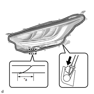
(e) Check the installation condition of the headlight lens gasket.
NOTICE:
Make sure the headlight lens gasket is not protruding and completely contacts the headlight lens sub-assembly.
7. INSTALL NO. 1 HEADLIGHT COVER
(a) Install the No. 1 headlight cover as shown in the illustration.
|
| Install in this Direction |
8. INSTALL HEADLIGHT LEVELING MOTOR BASE PACKING
| (a) Install a new headlight leveling motor base packing. |
|
.png)
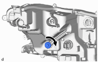
9. INSTALL HEADLIGHT LEVELING MOTOR
(a) Install the headlight leveling motor as shown in the illustration.
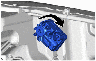
|
| Install in this Direction |
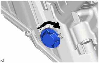
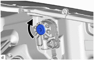
| (b) Turn the aiming screw as shown in the illustration. HINT: Turn the aiming screw the same number of times as they were turned during removal. |
|
 Adjustment
ADJUSTMENT PROCEDURE 1. PREPARE VEHICLE FOR HEADLIGHT AIM ADJUSTMENT (a) Prepare the vehicle:
Ensure that the vehicle body is not damaged or deformed around the headlights...
 Installation
INSTALLATION CAUTION / NOTICE / HINT HINT:
Use the same procedure for the RH side and LH side.
The following procedure is for the LH side.
PROCEDURE 1...
Other information:
Toyota Yaris XP210 (2020-2026) Owner's Manual: Accessory Socket
Only use genuine Toyota accessories or the equivalent requiring no greater than 120 W (DC 12 V, 10 A). The ignition must be switched to ACC or ON. Type A Type B NOTICE To prevent accessory socket damage or electrical failure, pay attention to the following: Do not use accessories that require more than 120 W (DC 12 V, 10 A)...
Toyota Yaris XP210 (2020-2026) Reapir and Service Manual: Installation
INSTALLATION CAUTION / NOTICE / HINT NOTICE: When replacing the windshield glass of a vehicle equipped with a forward recognition camera, make sure to use a Toyota genuine part. If a non-Toyota genuine part is used, the forward recognition camera may not be able to be installed due to a missing bracket...
Categories
- Manuals Home
- Toyota Yaris Owners Manual
- Toyota Yaris Service Manual
- Engine & Hybrid System
- Power Integration No.1 System Missing Message (B235287,B235587,B235787-B235987)
- How to connect USB port/Auxiliary jack
- New on site
- Most important about car
Front Seat Belt Pretensioners
The front seat belt pretensioners are designed to deploy in moderate or severe frontal, near frontal collisions.
In addition, the pretensioners operate when a side collision or a rollover accident is detected. The pretensioners operate differently depending on what types of air bags are equipped. For more details about the seat belt pretensioner operation, refer to the SRS Air Bag Deployment Criteria.