Toyota Yaris: Steering Column Assembly / Reassembly
REASSEMBLY
CAUTION / NOTICE / HINT
NOTICE:
- Do not drop the power steering ECU assembly, strike it with tools or subject it to impacts.
- If the power steering ECU assembly is subjected to an impact, replace it with a new one.
- Do not pull the wire harness.
- Do not allow any moisture to come into contact with the power steering ECU assembly.
- Do not loosen any bolts not mentioned in the procedure.
- Do not allow any foreign matter to contaminate the power steering ECU assembly.
PROCEDURE
1. INSTALL ELECTRIC POWER STEERING MOTOR SHAFT DAMPER
Click here

2. INSTALL POWER STEERING ECU ASSEMBLY
Click here

3. INSTALL STEERING LOCK ACTUATOR OR UPPER BRACKET ASSEMBLY
NOTICE:
When replacing the steering lock actuator or upper bracket assembly, perform code registration.
Click here

(a) Secure the steering column assembly in a vise between aluminum plates.
NOTICE:
Do not overtighten the vise.
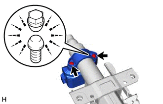
(b) Temporarily install the steering lock actuator or upper bracket assembly and upper steering column clamp with 2 new steering lock set bolts.
| (c) Tighten the 2 steering lock set bolts until the bolt head breaks off. |
|
 Inspection
INSPECTION PROCEDURE 1. INSPECT PRELOAD (a) Secure the steering column assembly in a vise using aluminum plates, cloths and wooden blocks. NOTICE:
Do not overtighten the vise, as the steering column assembly may become deformed...
 Steering Heater Switch
ComponentsCOMPONENTS ILLUSTRATION
*1 STEERING HEATER SWITCH - - RemovalREMOVAL PROCEDURE 1. REMOVE LOWER INSTRUMENT PANEL FINISH PANEL ASSEMBLY Click here
2...
Other information:
Toyota Yaris XP210 (2020-2026) Reapir and Service Manual: Charge Air Cooler Temperature Sensor Bank 1 Circuit Short to Ground (P007A11)
DESCRIPTION The intake air temperature sensor, built into the No. 2 turbo pressure sensor, monitors the intake air temperature. The intake air temperature sensor has a built-in thermistor with a resistance that varies according to the temperature of the intake air...
Toyota Yaris XP210 (2020-2026) Reapir and Service Manual: Data List / Active Test
DATA LIST / ACTIVE TEST NOTICE: In the table below, the values listed under "Normal Condition" are reference values. Do not depend solely on these reference values when deciding whether a part is faulty or not. When diagnosing symptoms such as hesitation, rough idle, or other small symptoms using vehicle control history, compare data extracted from the same vehicle model in the same conditions and make sure to analyze all data in its entirety before making a diagnosis...
Categories
- Manuals Home
- Toyota Yaris Owners Manual
- Toyota Yaris Service Manual
- Battery Monitor Module General Electrical Failure (P058A01)
- Opening and Closing the Liftgate/Trunk Lid
- Fuel Gauge
- New on site
- Most important about car
Front Seat Belt Pretensioners
The front seat belt pretensioners are designed to deploy in moderate or severe frontal, near frontal collisions.
In addition, the pretensioners operate when a side collision or a rollover accident is detected. The pretensioners operate differently depending on what types of air bags are equipped. For more details about the seat belt pretensioner operation, refer to the SRS Air Bag Deployment Criteria.