Toyota Yaris: Steering Column Assembly / Inspection
INSPECTION
PROCEDURE
1. INSPECT PRELOAD
| (a) Secure the steering column assembly in a vise using aluminum plates, cloths and wooden blocks. NOTICE:
|
|
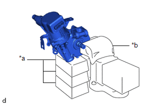
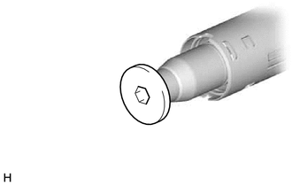
| (b) Using a 10 mm hexagon socket wrench, install the steering wheel assembly set bolt to the steering main shaft. NOTICE: Do not apply excessive torque to the steering wheel assembly set bolt by using a tool such as an impact wrench. HINT: The steering wheel assembly set bolt is used for turning the steering main shaft during inspection of the steering main shaft rotating torque. Remove the steering wheel assembly set bolt after performing this inspection. |
|
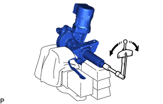
(c) Using a torque wrench, turn the steering main shaft at a constant rate of approximately 1 revolution every 4 seconds and measure the preload.
Preload:
1.0 to 2.2 N*m (11 to 22 kgf*cm, 9 to 19 in.*lbf)
If the preload is not as specified, replace the power steering ECU assembly or electric power steering column sub-assembly with a new one.
 | Turn |
(d) Remove the steering wheel assembly set bolt.
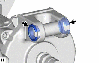
2. INSPECT STEERING COLUMN ASSEMBLY
| (a) Check that the 2 bushings are securely installed to the steering column assembly. If the bushings are deformed, missing or damaged, replace the electric power steering column sub-assembly with a new one. |
|
 Disassembly
DISASSEMBLY CAUTION / NOTICE / HINT NOTICE:
Do not drop the power steering ECU assembly, strike it with tools or subject it to impacts.
If the power steering ECU assembly is subjected to an impact, replace it with a new one...
 Reassembly
REASSEMBLY CAUTION / NOTICE / HINT NOTICE:
Do not drop the power steering ECU assembly, strike it with tools or subject it to impacts.
If the power steering ECU assembly is subjected to an impact, replace it with a new one...
Other information:
Toyota Yaris XP210 (2020-2026) Reapir and Service Manual: Removal
REMOVAL CAUTION / NOTICE / HINT The necessary procedures (adjustment, calibration, initialization, or registration) that must be performed after parts are removed, installed, or replaced during the engine assembly removal/installation are shown below...
Toyota Yaris XP210 (2020-2026) Reapir and Service Manual: How To Proceed With Troubleshooting
CAUTION / NOTICE / HINT HINT: *: Use the GTS. PROCEDURE 1. VEHICLE BROUGHT TO WORKSHOP NEXT 2. CUSTOMER PROBLEM ANALYSIS NEXT 3. CONNECT GTS TO DLC3* HINT: If the display indicates a communication malfunction, inspect the DLC3...
Categories
- Manuals Home
- Toyota Yaris Owners Manual
- Toyota Yaris Service Manual
- How to connect USB port/Auxiliary jack
- Fuel Gauge
- Auto Lock/Unlock Function
- New on site
- Most important about car
Turning the Engine Off
Stop the vehicle completely. Manual transaxle: Shift into neutral and set the parking brake.Automatic transaxle: Shift the selector lever to the P position and set the parking brake.
Press the push button start to turn off the engine. The ignition position is off.