Toyota Yaris: Front Drive Shaft Assembly / Removal
REMOVAL
CAUTION / NOTICE / HINT
The necessary procedures (adjustment, calibration, initialization, or registration) that must be performed after parts are removed and installed, or replaced during the front drive shaft assembly removal/installation are shown below.
Necessary Procedures After Parts Removed/Installed/Replaced| Replaced Part or Performed Procedure | Necessary Procedure | Effect/Inoperative Function when Necessary Procedure not Performed | Link |
|---|---|---|---|
| Front wheel alignment adjustment | ECU Data Initialization | Active torque split AWD system |
|
| Calibration |
|
|


HINT:
- Use the same procedure for the RH side and LH side.
- The following procedure is for the LH side.
PROCEDURE
1. REMOVE FRONT WHEEL
Click here

2. REMOVE NO. 1 ENGINE UNDER COVER ASSEMBLY
Click here

3. REMOVE ENGINE UNDER COVER LH
Click here

4. REMOVE ENGINE UNDER COVER RH
HINT:
Use the same procedure as for the LH side.
5. DRAIN MANUAL TRANSAXLE OIL
Click here

6. DRAIN TRANSFER OIL
Click here

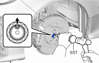
7. REMOVE FRONT AXLE SHAFT NUT
| (a) Using SST and a hammer, release the staked part of the front axle shaft nut. SST: 09930-00010 NOTICE: Loosen the staked part of the front axle shaft nut completely, otherwise the threads of the front drive shaft assembly may be damaged. |
|
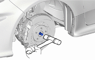
(b) Using a 30 mm deep socket wrench, remove the front axle shaft nut while applying the brakes.
8. SEPARATE FRONT SPEED SENSOR
Click here

9. SEPARATE TIE ROD END SUB-ASSEMBLY
Click here

10. SEPARATE FRONT STABILIZER LINK ASSEMBLY
Click here

11. SEPARATE FRONT LOWER NO.1 SUSPENSION ARM SUB-ASSEMBLY
Click here

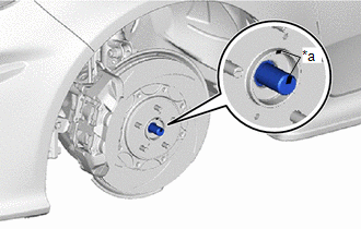
12. SEPARATE FRONT DRIVE SHAFT ASSEMBLY
| (a) Put matchmarks on the front drive shaft assembly and the front axle hub sub-assembly. |
|
| (b) Using a plastic hammer, separate the front drive shaft assembly from the front axle hub sub-assembly. NOTICE:
HINT: If it is difficult to separate the front drive shaft assembly from the front axle hub sub-assembly, tap the end of the front drive shaft assembly using a brass bar and a hammer. |
|
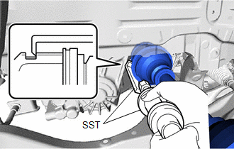
13. REMOVE FRONT DRIVE SHAFT ASSEMBLY LH
| (a) Using SST, remove the front drive shaft assembly LH. SST: 09520-01011 SST: 09520-20010 09521-02010 09521-02040 09521-02060 NOTICE:
|
|
14. REMOVE FRONT DRIVE SHAFT ASSEMBLY RH
| (a) Separate the drive shaft bearing bracket hole snap ring from the drive shaft bearing bracket. |
|
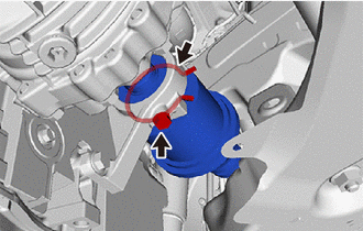
(b) Remove the bolt and front drive shaft assembly RH from the drive shaft bearing bracket.
NOTICE:
- Do not damage the transfer case oil seal RH.
- Do not damage the front drive shaft oil seal RH.
- Do not drop the front drive shaft assembly RH.
- When removing the front drive shaft assembly RH, keep it level.
HINT:
If the spline connection is stiff, using a brass bar and hammer, lightly tap the inboard joint assembly to remove it.
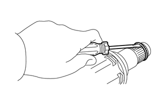
15. REMOVE FRONT DRIVE SHAFT HOLE SNAP RING LH
| (a) Using a screwdriver, remove the front drive shaft hole snap ring LH from the front drive shaft assembly LH. |
|
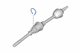
16. REMOVE DRIVE SHAFT BEARING BRACKET HOLE SNAP RING
| (a) Remove the drive shaft bearing bracket hole snap ring from the front drive shaft assembly RH. |
|
 Components
COMPONENTS ILLUSTRATION
*1 NO. 1 ENGINE UNDER COVER ASSEMBLY *2 ENGINE UNDER COVER LH *3 ENGINE UNDER COVER RH - -
N*m (kgf*cm, ft...
 Disassembly
DISASSEMBLY CAUTION / NOTICE / HINT NOTICE:
When using a vise, place aluminum plates between the part and vise.
When using a vise, do not overtighten it...
Other information:
Toyota Yaris XP210 (2020-2026) Reapir and Service Manual: Crankshaft Position Sensor "A" Circuit Short to Ground (P033511,P033515)
DESCRIPTION The crankshaft position sensor system consists of a crankshaft position sensor plate and Magneto-Resistive Element (MRE) type sensor. The crankshaft position sensor plate has 34 teeth at 10° intervals (2 teeth are missing for detecting top dead center), and is installed on the crankshaft...
Toyota Yaris XP210 (2020-2026) Owner's Manual: Contact Your Toyota Dealer and Have Vehicle Inspected
If any of the following warning lights turns on/flashes, the system may have a malfunction. Contact your Toyota dealer to have your vehicle inspected. ABS Warning Light When the engine is jump-started to charge the battery, uneven rpm occurs and the ABS warning light may illuminate...
Categories
- Manuals Home
- Toyota Yaris Owners Manual
- Toyota Yaris Service Manual
- Opening and Closing the Liftgate/Trunk Lid
- Engine & Hybrid System
- Immobilizer System
- New on site
- Most important about car
Front Seat Belt Pretensioners
The front seat belt pretensioners are designed to deploy in moderate or severe frontal, near frontal collisions.
In addition, the pretensioners operate when a side collision or a rollover accident is detected. The pretensioners operate differently depending on what types of air bags are equipped. For more details about the seat belt pretensioner operation, refer to the SRS Air Bag Deployment Criteria.