Toyota Yaris: Steering Column / Steering Heater Switch
Components
COMPONENTS
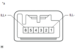
ILLUSTRATION
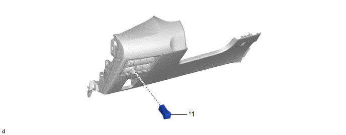
| *1 | STEERING HEATER SWITCH | - | - |
Removal
REMOVAL
PROCEDURE
1. REMOVE LOWER INSTRUMENT PANEL FINISH PANEL ASSEMBLY
Click here

2. REMOVE STEERING HEATER SWITCH
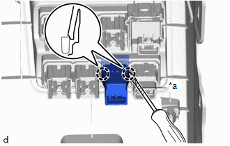
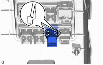
| (a) Using a screwdriver with its tip wrapped with protective tape, disengage the claws to remove the steering heater switch. |
|
Inspection
INSPECTION
PROCEDURE
1. INSPECT STEERING HEATER SWITCH
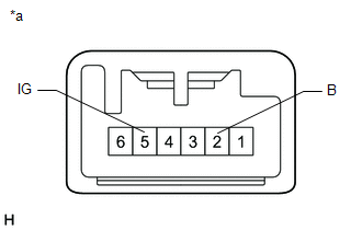
(a) Check the resistance.
| (1) Measure the resistance according to the value(s) in the table below. Standard Resistance:
If the result is not as specified, replace the steering heater switch. |
|
(b) Check the indicator.
| (1) Apply auxiliary battery voltage to the steering heater switch and check that the indicator illuminates. OK:
If the result is not as specified, replace the steering heater switch. |
|
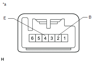
(c) Check the illumination.
| (1) Apply auxiliary battery voltage to the steering heater switch and check that the illumination. OK:
If the result is not as specified, replace the steering heater switch. |
|
Installation
INSTALLATION
PROCEDURE
1. INSTALL STEERING HEATER SWITCH
| (a) Engage the claws to install the steering heater switch. |
|
2. INSTALL LOWER INSTRUMENT PANEL FINISH PANEL ASSEMBLY
Click here

 Reassembly
REASSEMBLY CAUTION / NOTICE / HINT NOTICE:
Do not drop the power steering ECU assembly, strike it with tools or subject it to impacts.
If the power steering ECU assembly is subjected to an impact, replace it with a new one...

Other information:
Toyota Yaris XP210 (2020-2026) Reapir and Service Manual: Lost Communication With ECM/PCM "A" Missing Message (U010087,U010187,U012687,U012987,U014087,U015587)
DESCRIPTION When a malfunction is detected between various ECUs and sensors, these DTCs are stored. DTC No. Detection Item DTC Detection Condition Trouble Area U010087 Lost Communication With ECM/PCM "A" Missing Message When the ignition switch is ON for 3 seconds or more, and the vehicle is being driven at a speed of 5 km/h (3mph) or more, a communication malfunction between the forward recognition camera and the ECM continues for 2 seconds or more...
Toyota Yaris XP210 (2020-2026) Reapir and Service Manual: Data List / Active Test
DATA LIST / ACTIVE TEST DATA LIST NOTICE: In the table below, the values listed under "Normal Condition" are reference values. Do not depend solely on these reference values when deciding whether a part is faulty or not. HINT: Using the GTS to read the Data List allows the values or states of switches, sensors, actuators and other items to be read without removing any parts...
Categories
- Manuals Home
- Toyota Yaris Owners Manual
- Toyota Yaris Service Manual
- How to use USB mode
- Diagnostic Trouble Code Chart
- Removal
- New on site
- Most important about car
Keys

To use the auxiliary key, press the knob and pull out the auxiliary key from the smart key.
