Toyota Yaris: Vehicle Stability Control System / Precaution
PRECAUTION
HANDLING PRECAUTION
(a) Always ensure that the ignition switch is off before removing the brake actuator assembly or a sensor unless specifically instructed by the repair manual.
(b) When replacing the brake actuator assembly, always replace it with a new one.
NOTICE:
Never use a brake actuator assembly from another vehicle, including new vehicles.
(c) When replacing the brake actuator assembly, always check that ECU security key is registered.
Click here

(d) If the brake actuator assembly or a sensor has been removed and installed, always perform a Dealer Mode (Signal Check) inspection and check for DTCs after completion of installation to confirm that the system is operating correctly.
(e) Do not remove and install any vehicle stability control system components not specified by the repair manual or the system may not operate correctly due to loss of calibration.
(f) When performing diagnosis and repair for the vehicle stability control system, follow all specified procedures and perform the necessary inspections after completion.
DTC PRECAUTION
(a) If the warning lights are illuminated due to a malfunction, the warning lights will only turn off for some DTCs when the malfunction is repaired and the DTCs are cleared.
(b) If a warning lights are illuminated, it is necessary to follow the procedure to turn off the warning lights.
Warning Clearing Procedure| DTC No. | Procedure |
|---|---|
| C05001F C050023 C05003A C05061F C050623 C05063A C050C1F C050C23 C050C3A C05121F C051223 C05123A C05201C C052096 |
|
| C13807E C13807F P057111 |
|
| C052696 C14FE14 |
|
| C006396 |
|
NOTICE:
- Use caution when operating the vehicle when the warning lights are illuminated as the system may not operate due to a fail-safe function.
- After clearing the DTCs, the DTCs will be stored again if the malfunction persists.
PRECAUTION FOR REPLACE STEERING SENSOR
NOTICE:
After replacing the steering sensor, check that ECU security key is registered.
Click here

CHASSIS DYNAMOMETER PRECAUTION
When testing with a 2-wheel drum tester such as a speedometer tester, combination tester for the speedometer and brakes, or chassis dynamometer, or when jacking up the front wheels and turning the wheels, perform the following procedure to enter Inspection Mode and disable the TRC and VSC systems.
CAUTION:
-
Do not use the drum tester with any of the lock chains disconnected.
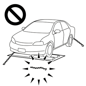
- Using the drum tester with a lock chain disconnected could cause the vehicle to begin moving unexpectedly.
-
Do not use the drum tester while the TRC or VSC is able to operate.
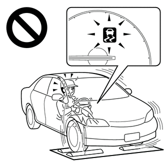
- TRC or VSC operation could cause the vehicle to begin moving unexpectedly.
NOTICE:
Secure the vehicle with lock chains for safety.
HINT:
If Inspection Mode is not used, the vehicle may unexpectedly move off the dynamometer because of TRC and VSC operation.
(a) Activating Inspection Mode (When Using the GTS)
(1) Ensure that the ignition switch is off and the engine is stopped.
(2) Connect the GTS to the DLC3.
(3) Turn the ignition switch to ON.
(4) Turn the GTS on.
(5) Operate the GTS to enter the Inspection Mode.
Chassis > Brake > Utility| Tester Display |
|---|
| Inspection Mode |
(6) Check that the VSC OFF indicator light comes on and the TRC OFF message is displayed on the multi-information display.
NOTICE:
Turn the ignition switch off when 60 seconds or more have elapsed since Inspection Mode was entered. If the ignition switch is turned off before 60 seconds or more elapse, Inspection Mode continues when the ignition switch is turned to ON.
HINT:
- If the VSC OFF indicator light does not come on and the TRC OFF message is not displayed on the multi-information display, repeat the steps above.
- Turning the ignition switch off ends Inspection Mode.
(b) Activating Inspection Mode (When not Using the GTS)
HINT:
Perform steps "C" to "G" within 30 seconds.
(1) Ensure that the ignition switch is off and the engine is stopped (Step "A").
(2) Release the parking brake (Step "B").
(3) With the brake pedal depressed, start the engine (Step "C").
(4) While holding the brake pedal down, apply the parking brake (Step "D").
(5) With the parking brake applied, depress and release the brake pedal twice (Step "E").
(6) While holding the brake pedal down, release and apply the parking brake twice (Step "F").
(7) With the parking brake applied, depress and release the brake pedal twice (Step "G").
(8) Check that the VSC OFF indicator light comes on and the TRC OFF message is displayed on the multi-information display (Step "H").
NOTICE:
Turn the ignition switch off when 60 seconds or more have elapsed since Inspection Mode was entered. If the ignition switch is turned off before 60 seconds or more elapse, Inspection Mode continues when the ignition switch is turned to ON.
HINT:
- If the VSC OFF indicator light does not come on and the TRC OFF message is not displayed on the multi-information display in step "H", repeat steps "A" to "H".
- Turning the ignition switch off ends Inspection Mode.

 Parts Location
PARTS LOCATION ILLUSTRATION
*1 FRONT AXLE HUB SUB-ASSEMBLY RH - FRONT SPEED SENSOR ROTOR RH *2 FRONT SPEED SENSOR RH *3 REAR AXLE HUB AND BEARING ASSEMBLY RH - REAR SPEED SENSOR ROTOR RH *4 REAR SPEED SENSOR RH *5 REAR AXLE HUB AND BEARING ASSEMBLY LH - REAR SPEED SENSOR ROTOR LH *6 REAR SPEED SENSOR LH *7 FRONT AXLE HUB SUB-ASSEMBLY LH - FRONT SPEED SENSOR ROTOR LH *8 FRONT SPEED SENSOR LH ILLUSTRATION
*1 ECM *2 NO...
Other information:
Toyota Yaris XP210 (2020-2026) Reapir and Service Manual: Diagnostic Trouble Code Chart
D..
Toyota Yaris XP210 (2020-2026) Reapir and Service Manual: Lost Communication With ECM/PCM "A" Missing Message (U010087,U011487,U012987,U013187,U014087,U015187,U016887,U023587,U023A87,U111287,U113387)
DESCRIPTION The combination meter assembly communicates with each ECU via CAN communication. DTC No. Detection Item DTC Detection Condition Trouble Area U010087 Lost Communication With ECM/PCM "A" Missing Message Diagnosis Condition: The ignition switch is ON IG power source voltage is 9...
Categories
- Manuals Home
- Toyota Yaris Owners Manual
- Toyota Yaris Service Manual
- Maintenance
- Headlights
- Immobilizer System
- New on site
- Most important about car
Fuel Gauge
The fuel gauge shows approximately how much fuel is remaining in the tank when the ignition is switched ON. We recommend keeping the tank over 1/4 full.
