Toyota Yaris: Can Communication System / Precaution
PRECAUTION
CAN COMMUNICATION SYSTEM TROUBLESHOOTING
(a) Because the order of diagnosis is important to allow correct diagnosis, make sure to begin troubleshooting using How to Proceed with Troubleshooting when CAN communication system related DTCs are output.
Click here

(b) Precaution for steering system handling
(1) Be careful when replacing parts. Incorrect replacement could affect the performance of the steering system and result in hazardous driving.
Click here

(c) Precaution for SRS airbag system handling
NOTICE:
This vehicle is equipped with a Supplemental Restraint System (SRS) which includes parts such as airbags for the driver and front passenger. Failure to carry out service operations in the correct sequence could cause unexpected SRS deployment during servicing and may cause a serious accident. Before servicing (including removal or installation of parts, inspection or replacement), be sure to read Precaution for SRS.
Click here

(d) Precaution for when disconnecting a wire harness from a CAN junction connector
(1) When disconnecting a wire harness from a CAN junction connector, use tape or tags to identify each connector and make sure to reconnect each connector to its original location on the CAN junction connector.
HINT:
- Reconnecting a connector to a location other than its original location on the CAN junction connector will not affect system performance. However, reconnecting connectors to their original locations makes future maintenance easier and avoids negative effects on wire harnesses, such as excessive tension.
-
For information on how to identify the ECUs or sensors connected to the CAN junction connector, refer to Terminals of ECU.
Click here

(e) Bus line repair
(1) After repairing a bus line with solder, wrap the repaired area with electrical tape.
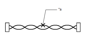
| *a | Soldered Area to Be Wrapped with Electrical Tape |
NOTICE:
- When installing, make sure that these lines are twisted, because CAN bus lines are likely to be influenced by electrical noise if the bus lines are not twisted.
- Ensure that there is no gap between the CANH wire and CANL wire.
- Make sure that the distance between the first twist of the wires and the connector is less than 80 mm (3.15 in).
- When repairing the CAN bus lines, do not change the length of the lines. (Make sure that the length of the CANH bus line and CANL bus line are the same.)
(2) Do not use bypass wiring between connectors.
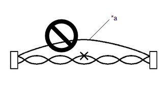
| *a | Bypass Wire |
NOTICE:
- The ability of the twisted bus lines to resist interference will be lost if bypass wiring is used.
- Do not use a twisted pair of wires for bypass wiring.
(f) Connector handling
(1) When checking resistance with a tester, insert the tester probes from the backside (harness side) of the connector.
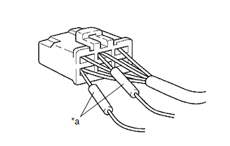
| *a | Tester Probe |
(2) When it is not possible to insert the tester from the backside of the connector, using service wires, measure from the front side of the connector.
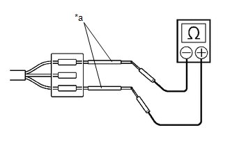
| *a | Service Wire |
(g) Precaution for when replacing a gateway function equipped ECU (sub bus monitoring ECU)
(1) When replacing a gateway equipped function ECU (sub bus monitoring ECU) with one which was installed to another vehicle, perform initialization of the sub bus monitoring ECU in order to clear stored bus information.
Click here

NOTICE:
If the stored bus information does not match the current sub bus configuration, DTCs may be stored and fail-safe functions may operate.
HINT:
It is not necessary to perform initialization of a gateway monitoring ECU (sub bus monitoring ECU) when using a sub bus monitoring ECU which was installed to another vehicle with the same sub bus configuration.
(h) Precautions for when a gateway function equipped ECU (sub bus monitor ECU) detects communication DTCs for ECUs not connected to the ECU
(1) Refer to precautions when replacing a gateway function equipped ECU (sub bus monitoring ECU) and initialize the connection information of the ECU.
(2) Clear the DTCs and check that no DTCs are output.
(i) Difference between genuine navigation receivers/radio and display receivers and optional navigation receivers/radio and display receivers
(1) Some optional navigation receivers/radio and display receivers are available as CAN compatible devices. Be aware that some optional navigation receivers/radio and display receivers do not have the same diagnostic features or characteristics of genuine navigation receivers/radio and display receivers.
NOTICE:
- Optional navigation receivers/radio and display receivers receive data from the CAN communication system. However, most optional navigation receivers/radio and display receivers do not send signals to the CAN bus main line.
- Most optional navigation receivers/radio and display receivers will not be displayed on the "CAN Bus Check" screen of the GTS.
- When checking for DTCs using the GTS, DTCs for optional navigation receivers/radio and display receivers will not be displayed on the GTS.
SENSOR EXPRESSIONS
(a) The descriptions for the blind spot monitor sensors differ depending on the system. The expressions listed in the table below are used in this Repair Manual.
| Part Name | Actual Part Name |
|---|---|
| Blind spot monitor sensor LH (B) | Blind spot monitor sensor LH |
| Blind spot monitor sensor RH (A) | Blind spot monitor sensor RH |

 Parts Location
PARTS LOCATION ILLUSTRATION
*1 FORWARD RECOGNITION CAMERA (w/ Toyota Safety Sense) *2 MILLIMETER WAVE RADAR SENSOR ASSEMBLY (w/ Toyota Safety Sense) *3 BRAKE ACTUATOR ASSEMBLY *4 ECM ILLUSTRATION
*1 4WD ECU ASSEMBLY - - ILLUSTRATION
*1 COMBINATION METER ASSEMBLY *2 METER MIRROR SUB-ASSEMBLY (w/ Headup Display) *3 CENTRAL GATEWAY ECU (NETWORK GATEWAY ECU) *4 MAIN BODY ECU (MULTIPLEX NETWORK BODY ECU) *5 AIR CONDITIONING AMPLIFIER ASSEMBLY *6 AIRBAG SENSOR ASSEMBLY *7 POWER STEERING ECU ASSEMBLY *8 CERTIFICATION ECU (SMART KEY ECU ASSEMBLY) *9 STEERING SENSOR *10 ENGINE STOP AND START ECU *11 STEREO COMPONENT EQUALIZER ASSEMBLY (w/ Active Noise Control System) *12 POWER DISTRIBUTION BOX ASSEMBLY *13 DLC3 - - ILLUSTRATION
*1 NO...
Other information:
Toyota Yaris XP210 (2020-2026) Reapir and Service Manual: Steering Lock Position Signal Compare Failure (B228562)
DESCRIPTION This DTC is stored when the steering lock position signal sent by the steering lock ECU (steering lock actuator or upper bracket assembly) via direct line and the steering lock position signal sent via LIN communication do not match. DTC No...
Toyota Yaris XP210 (2020-2026) Reapir and Service Manual: On-vehicle Inspection
ON-VEHICLE INSPECTION CAUTION / NOTICE / HINT The necessary procedures (adjustment, calibration, initialization or registration) that must be performed after parts are removed and installed, or replaced when repairing air leaks in the intake system are shown below...
Categories
- Manuals Home
- Toyota Yaris Owners Manual
- Toyota Yaris Service Manual
- Auto Lock/Unlock Function
- Battery Monitor Module General Electrical Failure (P058A01)
- How to use USB mode
- New on site
- Most important about car
Fuel Gauge
The fuel gauge shows approximately how much fuel is remaining in the tank when the ignition is switched ON. We recommend keeping the tank over 1/4 full.
