Toyota Yaris: Can Communication System / Parts Location
PARTS LOCATION
ILLUSTRATION
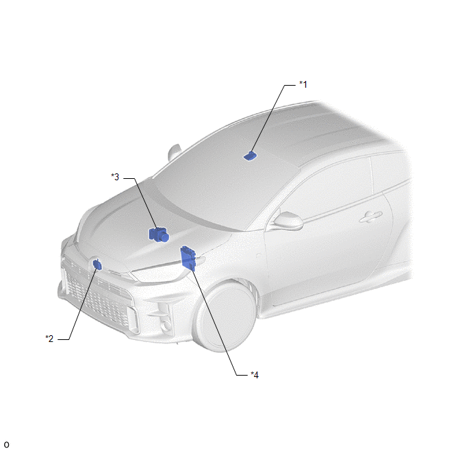
| *1 | FORWARD RECOGNITION CAMERA (w/ Toyota Safety Sense) | *2 | MILLIMETER WAVE RADAR SENSOR ASSEMBLY (w/ Toyota Safety Sense) |
| *3 | BRAKE ACTUATOR ASSEMBLY | *4 | ECM |
ILLUSTRATION
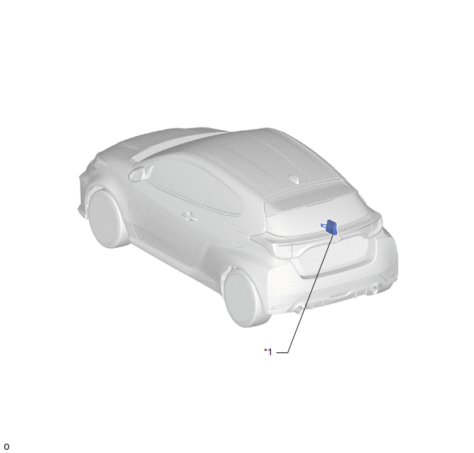
| *1 | 4WD ECU ASSEMBLY | - | - |
ILLUSTRATION
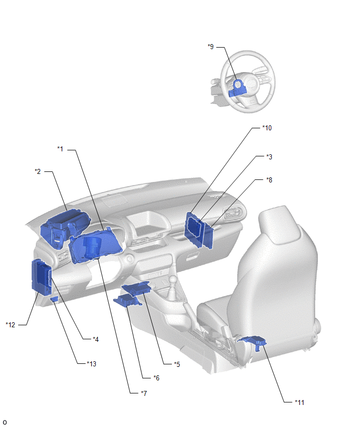
| *1 | COMBINATION METER ASSEMBLY | *2 | METER MIRROR SUB-ASSEMBLY (w/ Headup Display) |
| *3 | CENTRAL GATEWAY ECU (NETWORK GATEWAY ECU) | *4 | MAIN BODY ECU (MULTIPLEX NETWORK BODY ECU) |
| *5 | AIR CONDITIONING AMPLIFIER ASSEMBLY | *6 | AIRBAG SENSOR ASSEMBLY |
| *7 | POWER STEERING ECU ASSEMBLY | *8 | CERTIFICATION ECU (SMART KEY ECU ASSEMBLY) |
| *9 | STEERING SENSOR | *10 | ENGINE STOP AND START ECU |
| *11 | STEREO COMPONENT EQUALIZER ASSEMBLY (w/ Active Noise Control System) | *12 | POWER DISTRIBUTION BOX ASSEMBLY |
| *13 | DLC3 | - | - |
ILLUSTRATION
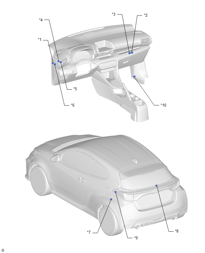
| *1 | NO. 1 GLOBAL CAN JUNCTION CONNECTOR | *2 | NO. 2 GLOBAL CAN JUNCTION CONNECTOR |
| *3 | NO. 3 GLOBAL CAN JUNCTION CONNECTOR | *4 | NO. 4 GLOBAL CAN JUNCTION CONNECTOR |
| *5 | NO. 6 GLOBAL CAN JUNCTION CONNECTOR | *6 | NO. 7 GLOBAL CAN JUNCTION CONNECTOR |
| *7 | NO. 8 GLOBAL CAN JUNCTION CONNECTOR | *8 | NO. 9 GLOBAL CAN JUNCTION CONNECTOR |
| *9 | NO. 1 CAN JUNCTION TERMINAL | *10 | OPTION CONNECTOR (BUS BUFFER ECU) |
 Precaution
PRECAUTION CAN COMMUNICATION SYSTEM TROUBLESHOOTING (a) Because the order of diagnosis is important to allow correct diagnosis, make sure to begin troubleshooting using How to Proceed with Troubleshooting when CAN communication system related DTCs are output...
 System Diagram
SYSTEM DIAGRAM (a) The CAN communication system is composed of 8 buses.
CAN Main Bus Line
Terminating Resistor
CAN Branch Line * Gateway Function Equipped ECU
Bus Monitoring Direction - - Connected to Code ECU/Sensor Name GTS Display Applicability - CGW Central Gateway ECU (Network Gateway ECU) - Installed on all vehicles - DLC3 DLC3 - Installed on all vehicles Bus 1 F-CAM Forward Recognition Camera Front Camera Module w/ Toyota Safety Sense F-MR Millimeter Wave Radar Sensor Assembly Front Radar w/ Toyota Safety Sense CAN Global J/C NO...
Other information:
Toyota Yaris XP210 (2020-2026) Reapir and Service Manual: Check Mode Procedure
CHECK MODE PROCEDURE CHECK MODE: DTC CHECK (a) Select "Check Mode" and proceed with checking using the GTS. Body Electrical > SRS Airbag > Utility Tester Display Check Mode NOTICE: Select Check Mode on the GTS to clear the DTCs (both current and history)...
Toyota Yaris XP210 (2020-2026) Reapir and Service Manual: Rain Sensor Malfunction (B1400)
DESCRIPTION This DTC is stored when the rain sensor detects an internal malfunction. DTC No. Detection Item DTC Detection Condition Trouble Area Memory DTC Output from B1400 Rain Sensor Malfunction IG power source voltage is 9...
Categories
- Manuals Home
- Toyota Yaris Owners Manual
- Toyota Yaris Service Manual
- How to connect USB port/Auxiliary jack
- Engine & Hybrid System
- To Set Speed
- New on site
- Most important about car
Break-In Period
No special break-in is necessary, but a few precautions in the first 600 miles (1,000 km) may add to the performance, economy, and life of the vehicle.
Do not race the engine. Do not maintain one constant speed, either slow or fast, for a long period of time. Do not drive constantly at full-throttle or high engine rpm for extended periods of time. Avoid unnecessary hard stops. Avoid full-throttle starts.