Toyota Yaris: Cxpi Communication System / Parts Location
PARTS LOCATION
ILLUSTRATION
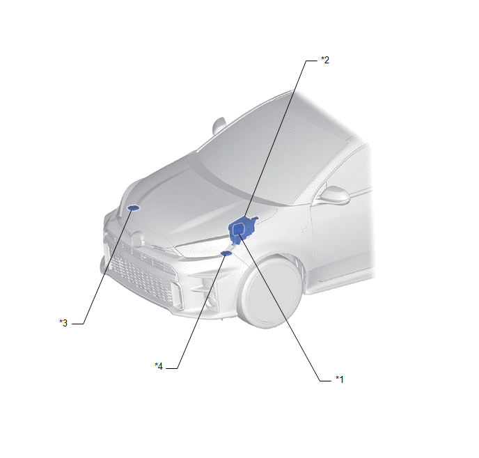
| *1 | SEMICONDUCTOR POWER INTEGRATION ECU | *2 | ENGINE ROOM RELAY BLOCK - STD P/I NO. 1 FUSE - INP STD NO. 1-1 FUSE - WASHER FUSE |
| *3 | LIGHT CONTROL LED ECU RH | *4 | LIGHT CONTROL LED ECU LH |
ILLUSTRATION
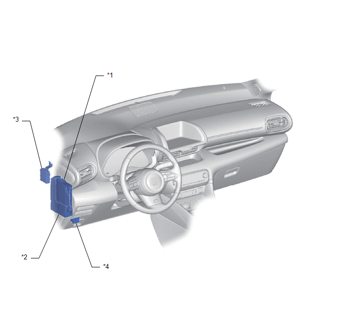
| *1 | MAIN BODY ECU (MULTIPLEX NETWORK BODY ECU) | *2 | POWER DISTRIBUTION BOX ASSEMBLY - ECU-IGR NO. 1 FUSE |
| *3 | WINDSHIELD WIPER RELAY ASSEMBLY | *4 | DLC3 |
 Precaution
PRECAUTION PRECAUTION FOR SEMICONDUCTOR POWER INTEGRATION ECU (a) Do not remove or install the semiconductor power integration ECU and power distribution box assembly with the negative (-) auxiliary battery terminal connected...
 System Diagram
S..
Other information:
Toyota Yaris XP210 (2020-2026) Reapir and Service Manual: Installation
INSTALLATION CAUTION / NOTICE / HINT HINT: Use the same procedure for the RH side and LH side. The following procedure is for the LH side. PROCEDURE 1. INSTALL ROOF DRIP SIDE FINISH MOULDING CLIP NOTICE: When installing a new roof drip side finish moulding clip, remove any double-sided tape remaining where the roof drip side finish moulding clips will be installed on the vehicle body and clean the vehicle body with a non-residue solvent...
Toyota Yaris XP210 (2020-2026) Owner's Manual: Bluetooth®
Bluetooth® Hands-Free outline When a Bluetooth® device (mobile phone) is connected to the vehicle’s Bluetooth® unit via radio wave transmission, a call can be made or received by pressing the talk button, pick-up button, or hang-up button on the audio remote control switch, or by operating the center display...
Categories
- Manuals Home
- Toyota Yaris Owners Manual
- Toyota Yaris Service Manual
- How to connect USB port/Auxiliary jack
- G16e-gts (engine Mechanical)
- Key Battery Replacement
- New on site
- Most important about car
Turning the Engine Off
Stop the vehicle completely. Manual transaxle: Shift into neutral and set the parking brake.Automatic transaxle: Shift the selector lever to the P position and set the parking brake.
Press the push button start to turn off the engine. The ignition position is off.
Copyright © 2026 www.toyaris4.com