Toyota Yaris: Lin Communication System / P/W Master SW System Missing Message (B120687,B232187,B232287)
DESCRIPTION
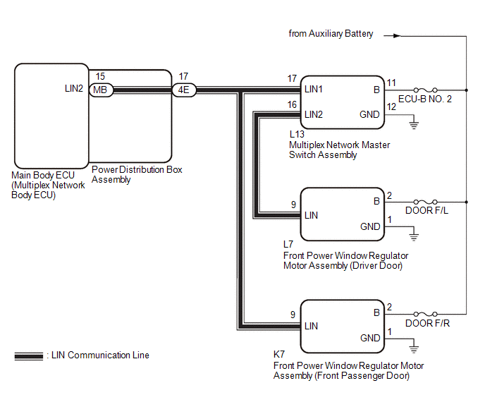
This DTC is stored when LIN communication between the main body ECU (multiplex network body ECU) and multiplex network master switch assembly, front power window regulator motor assembly (driver door), front power window regulator motor assembly (front passenger door) stops for 10 seconds or more.
| DTC No. | Detection Item | DTC Detection Condition | Trouble Area |
|---|---|---|---|
| B120687 | P/W Master SW System Missing Message | No communication between multiplex network master switch assembly and main body ECU (multiplex network body ECU) for 10 seconds or more. |
|
| B232187 | D-Door P/W System Missing Message | No communication between front power window regulator motor assembly (driver door) and main body ECU (multiplex network body ECU) for 10 seconds or more. |
|
| B232287 | P-Door P/W System Missing Message | No communication between front power window regulator motor assembly (front passenger door) and main body ECU (multiplex network body ECU) for 10 seconds or more. |
|
WIRING DIAGRAM
CAUTION / NOTICE / HINT
NOTICE:
- Inspect the fuses for circuits related to this system before performing the following procedure.
-
When a power window regulator motor assembly is replaced or removed and reinstalled, it is necessary to perform initialization.
Click here

-
Before replacing the main body ECU (multiplex network body ECU), refer to Registration.
Click here

PROCEDURE
| 1. | CLEAR DTC |
(a) Clear the DTCs.
Body Electrical > Main Body > Clear DTCs
|

| 2. | CHECK FOR DTC |
(a) Check for DTCs.
Body Electrical > Main Body > Trouble Codes| Result | Proceed to |
|---|---|
| DTC is B232588 output | A |
| DTC B120687, B232187 and B232287 are output | B |
| DTC B120687 and B232187 are output | C |
| Only DTC B120687 is output | D |
| Only DTC B232187 is output | E |
| Only DTC B232287 is output | F |
| DTC is not output | G |
| A |
 | GO TO DTC CHART |
| C |
 | GO TO STEP 5 |
| D |
 | GO TO STEP 6 |
| E |
 | GO TO STEP 7 |
| F |
 | GO TO STEP 10 |
| G |
 | USE SIMULATION METHOD TO CHECK |
|

| 3. | CHECK HARNESS AND CONNECTOR (POWER DISTRIBUTION BOX ASSEMBLY - MULTIPLEX NETWORK MASTER SWITCH ASSEMBLY) |
(a) Disconnect the 4E power distribution box assembly connector.
(b) Disconnect the L13 multiplex network master switch assembly connector.
(c) Measure the resistance according to the value(s) in the table below.
NOTICE:
Make sure that each ECU is in sleep mode before performing the inspection. To enter sleep mode, turn the ignition switch from ON to off and wait for 180 seconds or more without operating any switches.
Standard Resistance:
| Tester Connection | Condition | Specified Condition |
|---|---|---|
| 4E-17 - L13-17 (LIN1) | Always | Below 1 Ω |
| NG |
 | REPAIR OR REPLACE HARNESS OR CONNECTOR |
|

| 4. | INSPECT POWER DISTRIBUTION BOX ASSEMBLY |
(a) Remove the power distribution box assembly.
Click here

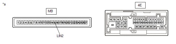
| *a | Component without harness connected (Power Distribution Box Assembly) | - | - |
(b) Remove the main body ECU (multiplex network body ECU) from the power distribution box assembly.
(c) Measure the resistance according to the value(s) in the table below.
HINT:
This inspection is to check the LIN communication line in the power distribution box assembly that connects the wire harness to the built-in main body ECU (multiplex network body ECU).
Standard Resistance:
| Tester Connection | Condition | Specified Condition |
|---|---|---|
| 4E-17 - MB-15 (LIN2) | Always | Below 1 Ω |
| OK |
 | REPLACE MAIN BODY ECU (MULTIPLEX NETWORK BODY ECU) |
| NG |
 | REPLACE POWER DISTRIBUTION BOX ASSEMBLY |
| 5. | CHECK HARNESS AND CONNECTOR (POWER DISTRIBUTION BOX ASSEMBLY - MULTIPLEX NETWORK MASTER SWITCH ASSEMBLY) |
(a) Disconnect the 4E power distribution box assembly connector.
(b) Disconnect the L13 multiplex network master switch assembly connector.
(c) Measure the resistance according to the value(s) in the table below.
NOTICE:
Make sure that each ECU is in sleep mode before performing the inspection. To enter sleep mode, turn the ignition switch from ON to off and wait for 180 seconds or more without operating any switches.
Standard Resistance:
| Tester Connection | Switch Condition | Specified Condition |
|---|---|---|
| 4E-17 - L13-17 (LIN1) | Ignition switch off | Below 1 Ω |
| OK |
 | REPLACE MULTIPLEX NETWORK MASTER SWITCH ASSEMBLY |
| NG |
 | REPAIR OR REPLACE HARNESS OR CONNECTOR |
| 6. | CHECK HARNESS AND CONNECTOR (MULTIPLEX NETWORK MASTER SWITCH ASSEMBLY - AUXILIARY BATTERY AND BODY GROUND) |
(a) Disconnect the L13 multiplex network master switch assembly connector.
(b) Measure the voltage according to the value(s) in the table below.
Standard Voltage:
| Tester Connection | Switch Condition | Specified Condition |
|---|---|---|
| L13-11 (B) - L13-12 (GND) | Ignition switch off | 11 to 14 V |
(c) Measure the resistance according to the value(s) in the table below.
Standard Resistance:
| Tester Connection | Condition | Specified Condition |
|---|---|---|
| L13-12 (GND) - Body ground | Always | Below 1 Ω |
| OK |
 | REPLACE MULTIPLEX NETWORK MASTER SWITCH ASSEMBLY |
| NG |
 | REPAIR OR REPLACE HARNESS OR CONNECTOR |
| 7. | CHECK HARNESS AND CONNECTOR (POWER DISTRIBUTION BOX ASSEMBLY - FRONT POWER WINDOW REGULATOR MOTOR ASSEMBLY (DRIVER DOOR)) |
(a) Disconnect the 4E power distribution box assembly connector.
(b) Disconnect the L7 front power window regulator motor assembly (driver door) connector.
(c) Measure the resistance according to the value(s) in the table below.
Standard Resistance:
| Tester Connection | Condition | Specified Condition |
|---|---|---|
| 4E-17 - L7-9 (LIN) | Always | Below 1 Ω |
| NG |
 | GO TO STEP 9 |
|

| 8. | CHECK HARNESS AND CONNECTOR (FRONT POWER WINDOW REGULATOR MOTOR ASSEMBLY (DRIVER DOOR) - AUXILIARY BATTERY AND BODY GROUND) |
(a) Disconnect the L7 front power window regulator motor assembly (driver door) connector.
(b) Measure the voltage according to the value(s) in the table below.
Standard Voltage:
| Tester Connection | Switch Condition | Specified Condition |
|---|---|---|
| L7-2 (B) - L7-1 (GND) | Ignition switch off | 11 to 14 V |
(c) Measure the resistance according to the value(s) in the table below.
Standard Resistance:
| Tester Connection | Condition | Specified Condition |
|---|---|---|
| L7-1 (GND) - Body ground | Always | Below 1 Ω |
| OK |
 | REPLACE FRONT POWER WINDOW REGULATOR MOTOR ASSEMBLY (DRIVER DOOR) |
| NG |
 | REPAIR OR REPLACE HARNESS OR CONNECTOR |
| 9. | CHECK HARNESS AND CONNECTOR (MULTIPLEX NETWORK MASTER SWITCH ASSEMBLY - FRONT POWER WINDOW REGULATOR MOTOR ASSEMBLY (DRIVER DOOR)) |
(a) Disconnect the L13 multiplex network master switch assembly connector.
(b) Disconnect the L7 front power window regulator motor assembly (driver door) connector.
(c) Measure the resistance according to the value(s) in the table below.
NOTICE:
Make sure that each ECU is in sleep mode before performing the inspection. To enter sleep mode, turn the ignition switch from ON to off and wait for 180 seconds or more without operating any switches.
Standard Resistance:
| Tester Connection | Condition | Specified Condition |
|---|---|---|
| 4E-17 - L7-9 (LIN) | Always | Below 1 Ω |
| OK |
 | REPLACE MULTIPLEX NETWORK MASTER SWITCH ASSEMBLY |
| NG |
 | REPAIR OR REPLACE HARNESS OR CONNECTOR |
| 10. | CHECK HARNESS AND CONNECTOR (POWER DISTRIBUTION BOX ASSEMBLY - FRONT POWER WINDOW REGULATOR MOTOR ASSEMBLY (FRONT PASSENGER DOOR)) |
(a) Disconnect the 4E power distribution box assembly connector.
(b) Disconnect the K7 front power window regulator motor assembly (front passenger door) connector.
(c) Measure the resistance according to the value(s) in the table below.
NOTICE:
Make sure that each ECU is in sleep mode before performing the inspection. To enter sleep mode, turn the ignition switch from ON to off and wait for 180 seconds or more without operating any switches.
Standard Resistance:
| Tester Connection | Switch Condition | Specified Condition |
|---|---|---|
| 4E-17 - K7-9 (LIN) | Ignition switch off | Below 1 Ω |
| NG |
 | REPAIR OR REPLACE HARNESS OR CONNECTOR |
|

| 11. | CHECK HARNESS AND CONNECTOR (FRONT POWER WINDOW REGULATOR MOTOR ASSEMBLY (FRONT PASSENGER DOOR) - AUXILIARY BATTERY AND BODY GROUND) |
(a) Disconnect the K7 front power window regulator motor assembly (front passenger door) connector.
(b) Measure the voltage according to the value(s) in the table below.
Standard Voltage:
| Tester Connection | Switch Condition | Specified Condition |
|---|---|---|
| K7-2 (B) - K7-1 (GND) | Ignition switch off | 11 to 14 V |
(c) Measure the resistance according to the value(s) in the table below.
Standard Resistance:
| Tester Connection | Condition | Specified Condition |
|---|---|---|
| K7-1 (GND) - Body ground | Always | Below 1 Ω |
| OK |
 | REPLACE FRONT POWER WINDOW REGULATOR MOTOR ASSEMBLY (FRONT PASSENGER DOOR) |
| NG |
 | REPAIR OR REPLACE HARNESS OR CONNECTOR |

 LIN Communication Missing Message (B228787)
DESCRIPTION When an internal malfunction is detected in the certification ECU (smart key ECU assembly), this DTC is stored. DTC No. Detection Item DTC Detection Condition Trouble Area B228787 LIN Communication Missing Message An internal malfunction occurs in the certification ECU (smart key ECU assembly)...
Other information:
Toyota Yaris XP210 (2020-2026) Reapir and Service Manual: Turbocharger/Supercharger Wastegate Solenoid "A" Circuit Open (P024313)
DESCRIPTION The waste gate valve is built into the turbine housing and is operated by the vacuum regulating valve assembly. The ECM uses duty control to open and close the vacuum regulating valve assembly. The amount of opening is controlled according to the operation status...
Toyota Yaris XP210 (2020-2026) Reapir and Service Manual: Installation
INSTALLATION CAUTION / NOTICE / HINT NOTICE: This procedure includes the installation of small-head bolts. Refer to Small-Head Bolts of Basic Repair Hint to identify the small-head bolts. Click here PROCEDURE 1. INSTALL TIMING GEAR COVER INSULATOR (a) Install the timing gear cover insulator to the cylinder blocke sub-assembly...
Categories
- Manuals Home
- Toyota Yaris Owners Manual
- Toyota Yaris Service Manual
- How to use USB mode
- Headlights
- To Set Speed
- New on site
- Most important about car
Turning the Engine Off
Stop the vehicle completely. Manual transaxle: Shift into neutral and set the parking brake.Automatic transaxle: Shift the selector lever to the P position and set the parking brake.
Press the push button start to turn off the engine. The ignition position is off.