Toyota Yaris: Rear Axle Hub / On-vehicle Inspection
ON-VEHICLE INSPECTION
CAUTION / NOTICE / HINT
HINT:
- Use the same procedure for the RH side and LH side.
- The following procedure is for the LH side.
PROCEDURE
1. REMOVE REAR WHEEL
Click here

2. SEPARATE REAR DISC BRAKE CALIPER ASSEMBLY
Click here

3. REMOVE PARKING BRAKE SHOE ADJUSTING HOLE PLUG
Click here

4. REMOVE REAR DISC
Click here

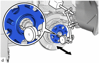
5. INSPECT REAR AXLE HUB BEARING LOOSENESS
| (a) Using a dial indicator, check for looseness near the center of the rear axle hub. Maximum Looseness: 0.05 mm (0.00197 in.) NOTICE:
HINT: If the looseness exceeds the maximum, replace the rear axle hub and bearing assembly. |
|
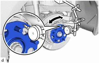
6. INSPECT REAR AXLE HUB RUNOUT
| (a) Using a dial indicator, check for runout on the surface of the rear axle hub outside the rear axle hub bolts. Maximum Runout: 0.05 mm (0.00197 in.) NOTICE:
HINT: If the runout exceeds the maximum, replace the rear axle hub and bearing assembly. |
|
7. INSTALL REAR DISC
Click here

8. ADJUST PARKING BRAKE SHOE CLEARANCE
Click here

9. INSTALL PARKING BRAKE SHOE ADJUSTING HOLE PLUG
Click here

10. INSTALL REAR DISC BRAKE CALIPER ASSEMBLY
Click here

11. INSPECT AND ADJUST PARKING BRAKE LEVER TRAVEL
Click here

12. INSTALL REAR WHEEL
Click here

 Components
COMPONENTS ILLUSTRATION
*1 REAR AXLE HUB AND BEARING ASSEMBLY *2 REAR AXLE SHAFT NUT *3 REAR DISC BRAKE CALIPER ASSEMBLY *4 REAR SPEED SENSOR *5 REAR FLEXIBLE HOSE *6 REAR DRIVE SHAFT ASSEMBLY *7 REAR DISC *8 PARKING BRAKE SHOE ADJUSTING HOLE PLUG
Tightening torque for "Major areas involving basic vehicle performance such as moving/turning/stopping" : N*m (kgf*cm, ft...
 Removal
REMOVAL CAUTION / NOTICE / HINT HINT:
Use the same procedure for the RH side and LH side.
The following procedure is for the LH side.
PROCEDURE 1...
Other information:
Toyota Yaris XP210 (2020-2026) Reapir and Service Manual: On-vehicle Inspection
ON-VEHICLE INSPECTION CAUTION / NOTICE / HINT CAUTION: When working near the engine room while the engine has started or the power source mode is engine switch on (IG), do not touch the fan and generator V belt or rotating components such as the fan, etc...
Toyota Yaris XP210 (2020-2026) Reapir and Service Manual: Terminals Of Ecu
TERMINALS OF ECU CHECK STEREO COMPONENT EQUALIZER ASSEMBLY Terminal No. (Symbol) Terminal Description Condition Specified Condition O131-15(+B) - O131-30(GND) Power source Always 11 to 14 V O131-29(IGP) - O131-30(GND) Power source (IG) Ignition switch ON 11 to 14 V O131-14(ACC) - O131-30(GND) Power source (ACC) Ignition switch ACC 11 to 14 V O131-30(GND) - Body ground Ground Always Below 1 Ω O132-1(MC1+) - O131-30(GND) Active noise control microphone input signal Active noise control microphone LH tapped with finger Pulse generation O132-5(MC1-) - O131-30(GND) Active noise control microphone input signal Always Below 1 Ω O132-2(MC2+) - O131-30(GND) Active noise control microphone input signal Active noise control microphone RH tapped with finger Pulse generation O132-6(MC2-) - O131-30(GND) Active noise control microphone input signal Always Below 1 Ω O131-3(NEI) - O131-30(GND) Engine pulse signal Idling with warm engine Pulse generation (See waveform 1) O131-24(FLI-) Active noise control microphone output signal - - O131-9(FLI+) Active noise control microphone output signal - - O131-23(FRI-) Active noise control microphone output signal - - O131-8(FRI+) Active noise control microphone output signal - - O131-5(RRI+) Active noise control microphone output signal - - O131-20(RRI-) Active noise control microphone output signal - - O131-6(RLI+) Active noise control microphone output signal - - O131-21(RLI-) Active noise control microphone output signal - - O131-7(ASG1) Shield ground - - O131-22(ASG2) Shield ground - - O131-12(FR+) - O131-30(GND) Sound signal Active noise control system operating Pulse generation O131-27(FR-) - O131-30(GND) Sound signal Active noise control system operating Pulse generation O131-13(FL+) - O131-30(GND) Sound signal Active noise control system operating Pulse generation O131-28(FL-) - O131-30(GND) Sound signal Active noise control system operating Pulse generation O131-10(RR+) - O131-30(GND) Sound signal Active noise control system operating Pulse generation O131+25(RR-) - O131-30(GND) Sound signal Active noise control system operating Pulse generation O131-11(RL+) - O131-30(GND) Sound signal Active noise control system operating Pulse generation O131-28(RL-) - O131-30(GND) Sound signal Active noise control system operating Pulse generation O131-1(CANH) CAN communication signal - - O131-16(CANL) CAN communication signal - - (a) Waveform 1 HINT: The oscilloscope waveform shown in the illustration is an example for reference only...
Categories
- Manuals Home
- Toyota Yaris Owners Manual
- Toyota Yaris Service Manual
- Removal
- Engine Start Function When Key Battery is Dead
- Maintenance
- New on site
- Most important about car
Fuel-Filler Lid and Cap
WARNING
When removing the fuel-filler cap, loosen the cap slightly and wait for any hissing to stop, then remove it
Fuel spray is dangerous. Fuel can burn skin and eyes and cause illness if ingested. Fuel spray is released when there is pressure in the fuel tank and the fuel-filler cap is removed too quickly.