Toyota Yaris: Rear Axle Hub / Removal
REMOVAL
CAUTION / NOTICE / HINT
HINT:
- Use the same procedure for the RH side and LH side.
- The following procedure is for the LH side.
PROCEDURE
1. REMOVE REAR WHEEL
Click here

2. REMOVE REAR AXLE SHAFT NUT
| (a) Using SST and a hammer, release the staked part of the rear axle shaft nut. SST: 09930-00010 NOTICE: Loosen the staked part of the rear axle shaft nut completely, otherwise the threads of the rear drive shaft assembly may be damaged. |
|
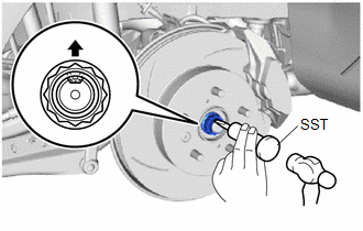
(b) While applying the brakes, remove the rear axle shaft nut.
3. SEPARATE REAR DISC BRAKE CALIPER ASSEMBLY
Click here

4. REMOVE PARKING BRAKE SHOE ADJUSTING HOLE PLUG
Click here

5. REMOVE REAR DISC
Click here

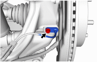
6. DISCONNECT REAR SPEED SENSOR
| (a) Remove the bolt and rear speed sensor from the rear axle carrier sub-assembly. NOTICE:
|
|
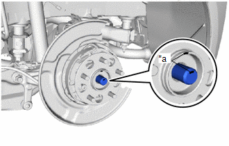
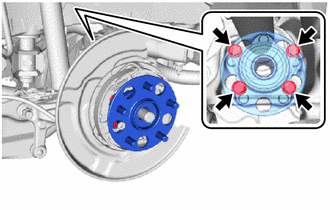
7. REMOVE REAR AXLE HUB AND BEARING ASSEMBLY
| (a) Put matchmarks on the rear drive shaft assembly and the rear axle hub and bearing assembly. |
|
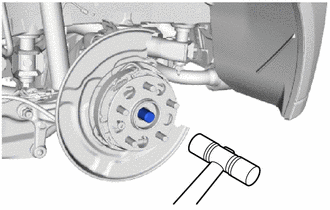
| (b) Using a plastic hammer, separate the rear drive shaft assembly from the rear axle hub and bearing assembly. NOTICE:
HINT: If it is difficult to separate the rear drive shaft assembly rear axle hub and bearing assembly, tap the end of the rear drive shaft assembly using a brass bar and a hammer. |
|
| (c) Remove the 4 bolts, rear axle hub and bearing assembly from the rear axle carrier sub-assembly. |
|
 On-vehicle Inspection
ON-VEHICLE INSPECTION CAUTION / NOTICE / HINT HINT:
Use the same procedure for the RH side and LH side.
The following procedure is for the LH side...
 Installation
INSTALLATION CAUTION / NOTICE / HINT HINT:
Use the same procedure for the RH side and LH side.
The following procedure is for the LH side.
PROCEDURE 1...
Other information:
Toyota Yaris XP210 (2020-2026) Reapir and Service Manual: Left Front Wheel Speed Sensor Supply Voltage Circuit Short to Ground or Open (C14E014,C14E314)
DESCRIPTION Refer to DTC C05001F. Click here DTC No. Detection Item DTC Detection Condition Trouble Area DTC Output from C14E014 Left Front Wheel Speed Sensor Supply Voltage Circuit Short to Ground or Open With the +BS terminal voltage 9...
Toyota Yaris XP210 (2020-2026) Reapir and Service Manual: Yaw Rate Sensor Signal Stuck In Range (C00632A,C05201C,C05202A,C052096)
DESCRIPTION The airbag sensor assembly has a built-in yaw rate and acceleration sensor and detects the vehicle condition. These DTCs are stored when the skid control ECU (brake actuator assembly) receives an internal malfunction signal from the yaw rate and acceleration sensor (airbag sensor assembly)...
Categories
- Manuals Home
- Toyota Yaris Owners Manual
- Toyota Yaris Service Manual
- Adjustment
- How to use USB mode
- How to connect USB port/Auxiliary jack
- New on site
- Most important about car
Fuel Gauge
The fuel gauge shows approximately how much fuel is remaining in the tank when the ignition is switched ON. We recommend keeping the tank over 1/4 full.
