Toyota Yaris: Intake System / On-vehicle Inspection
ON-VEHICLE INSPECTION
CAUTION / NOTICE / HINT
The necessary procedures (adjustment, calibration, initialization or registration) that must be performed after parts are removed and installed, or replaced when repairing air leaks in the intake system are shown below.
Necessary Procedures After Parts Removed/Installed/Replaced| Replaced Part or Performed Procedure | Necessary Procedure | Effect/Inoperative Function when Necessary Procedure not Performed | Link |
|---|---|---|---|
| Air leaks from intake system | Inspection After Repair |
|
|

PROCEDURE
1. INSPECT INTAKE SYSTEM
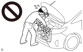
CAUTION:
To prevent injury due to contact with an operating cooling fan, keep your hands and clothing away from the cooling fans when working in the engine compartment with the engine running or the engine switch on (IG).
HINT:
Perform "Inspection After Repair" after repairing vacuum leaks in the intake system.
Click here

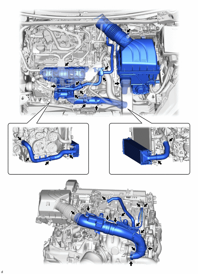
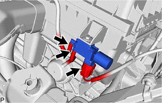
(a) Check that there are no vacuum leaks at the points shown in the illustration.
2. PERFORM INITIALIZATION
(a) Perform "Inspection After Repair" after repairing vacuum leaks in the intake system.
Click here

3. INSPECT INTAKE AIR CONTROL VALVE ACTUATOR
| (a) Disconnect the vacuum hose from the intake air control valve actuator. |
|
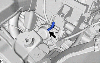
| (b) Confirm that the intake air control valve opens smoothly under vacuum and closes smoothly when the vacuum is released. If the intake air control valve does not close or open smoothly, replace the air cleaner assembly. |
|
(c) Connect the vacuum hose to the intake air control valve actuator.
4. INSPECT VACUUM SWITCHING VALVE ASSEMBLY (for AICV)
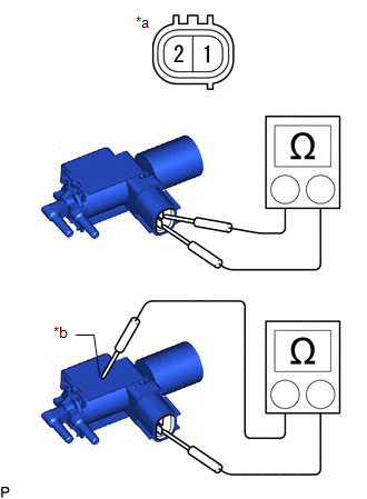
| (a) Disconnect the vacuum switching valve assembly (for AICV) connector. |
|
(b) Disconnect the 2 vacuum hoses from the vacuum switching valve assembly (for AICV).
| (c) Measure the resistance according to the value(s) in the table below. Standard Resistance:
If the result is not as specified, replace the air cleaner assembly. |
|
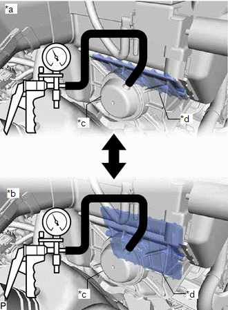
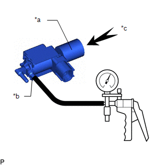
(d) Check the operation of the vacuum switching valve assembly (for AICV).
| (1) When vacuum is applied to the port (E), check that air is sucked into the filter. If air is not sucked into the filter, replace the air cleaner assembly. |
|
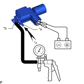
| (2) Apply battery voltage across the terminals. When vacuum is applied to the port (F), check that air is sucked into the port (E). If air is not sucked into the port (F), replace the air cleaner assembly. |
|

 Intercooler
ComponentsCOMPONENTS ILLUSTRATION
*1 RADIATOR SUPPORT SUB-ASSEMBLY UPPER *2 FRONT RADIATOR SIDE AIR GUIDE PLATE RH *3 FRONT RADIATOR SIDE AIR GUIDE PLATE LH *4 COOL AIR INTAKE DUCT *5 NO...
Other information:
Toyota Yaris XP210 (2020-2026) Reapir and Service Manual: On-vehicle Inspection
ON-VEHICLE INSPECTION PROCEDURE 1. INSPECT AUTOMATIC LIGHT CONTROL SENSOR (a) Check the wire harness. (1) Disconnect the automatic light control sensor. (2) Measure the voltage according to the value(s) in the table below. Standard Voltage: Tester Connection Switch Condition Specified Condition H78-1 (CLTB) - H78-2 (CLTE) Ignition switch on (IG) 11 to 14 V If the specified condition is not met, replace the vehicle wire harness...
Toyota Yaris XP210 (2020-2026) Reapir and Service Manual: Removal
REMOVAL CAUTION / NOTICE / HINT The necessary procedures (adjustment, calibration, initialization or registration) that must be performed after parts are removed and installed, or replaced during ECM removal/installation are shown below. Necessary Procedure After Parts Removed/Installed/Replaced Replacement Part or Procedure Necessary Procedures Effects/Inoperative when not performed Link *1: When the ECM is replaced with a new one, reset memory is unnecessary...
Categories
- Manuals Home
- Toyota Yaris Owners Manual
- Toyota Yaris Service Manual
- Key Battery Replacement
- Immobilizer System
- Brake System Control Module "A" System Voltage System Voltage Low (C137BA2)
- New on site
- Most important about car
Supplemental Restraint System (SRS) Precautions
The front and side supplemental restraint systems (SRS) include different types of air bags. Please verify the different types of air bags which are equipped on your vehicle by locating the “SRS AIRBAG” location indicators. These indicators are visible in the area where the air bags are installed.
The air bags are installed in the following locations:
The steering wheel hub (driver air bag) The front passenger dashboard (front passenger air bag) The outboard sides of the front seatbacks (side air bags) The front and rear window pillars, and the roof edge along both sides (curtain air bags)