Toyota Yaris: Balanceshaft / On-vehicle Inspection
ON-VEHICLE INSPECTION
PROCEDURE
1. REMOVE NO. 1 ENGINE UNDER COVER ASSEMBLY
Click here

2. DRAIN ENGINE OIL
Click here

3. DRAIN ENGINE COOLANT
Click here

4. REMOVE FAN AND GENERATOR V BELT
Click here

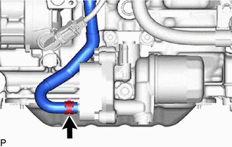
5. REMOVE OIL FILTER BRACKET SUB-ASSEMBLY
| (a) Slide the clip and separate the No. 6 water by-pass hose. |
|
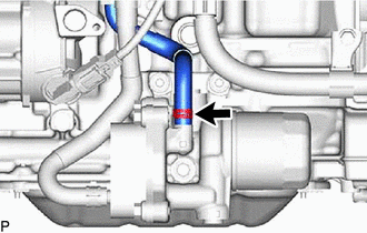
| (b) Slide the clip and separate the No. 5 water by-pass hose. |
|
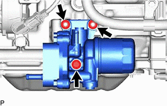
| (c) Remove the bolt, 2 nut and oil filter bracket sub-assembly from the cylinder block sub-aseembly. |
|
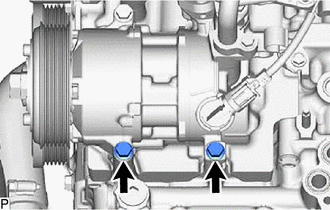
6. SEPARATE COMPRESSOR WITH PULLEY ASSEMBLY
| (a) Remove the 2 bolts and separate the compressor with pulley assembly. |
|
7. SEPARATE NO. 4 CYLINDER BROCK INSULATOR
| (a) Remove the bolt and separate the No. 4 cylinder brock insulator. |
|
8. REMOVE NO. 2 OIL PAN SUB-ASSEMBLY
Click here

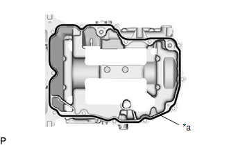
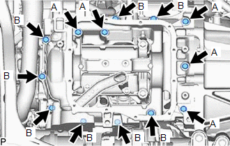
9. REMOVE OIL PAN SUB-ASSEMBLY
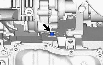
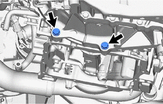
| (a) Remove the 2 bolts. |
|

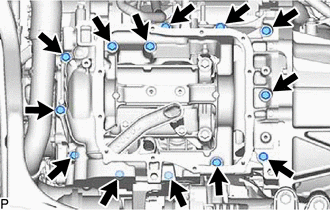
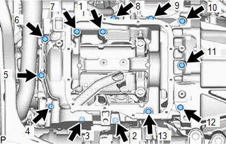
| (b) Remove the 13 bolts. |
|
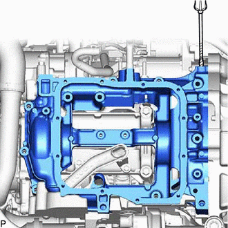
| (c) Using a screwdriver, remove the oil pan sub-assembly by prying between the oil pan sub-assembly and crankshaft bearing cap assembly at the places shown in the illustration. NOTICE: Be careful not to damage the contact surfaces of the crankshaft bearing cap sub-aseembly and oil pan sub-assembly.. |
|
(d) Remove the 2 o-rings from the crankshaft bearing cap assembly.
10. INSPECT BALANCESHAFT BACK LASH
| (a) Install a dial indicator and magnetic base. |
|
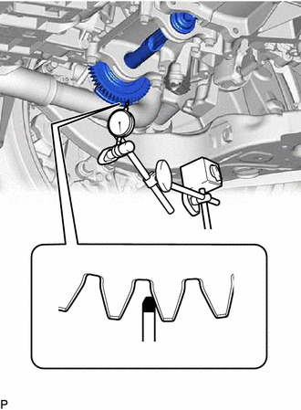
(b) Set the tip of the dial indicator to the position shown in the illustration.
(c) Push the balance shaft gear to one side and set the dial indicator to 0 point with the backlash blocked.
(d) Move the balance shaft gear by hand and measure the backlash with the dial indicator.
Standard Diameter:
0.055 to 0.105 mm (0.00217 to 0.00413 in.)
11. ADJUST BALANCESHAFT BACK LASH
(a) Remove the engine balancer assembly.
Click here

(b) Remove the balanceshaft housing spacer.
Click here

(c) If the result is not within the specified range, select balanceshaft housing spacer that are thicker or thinner as necessary.
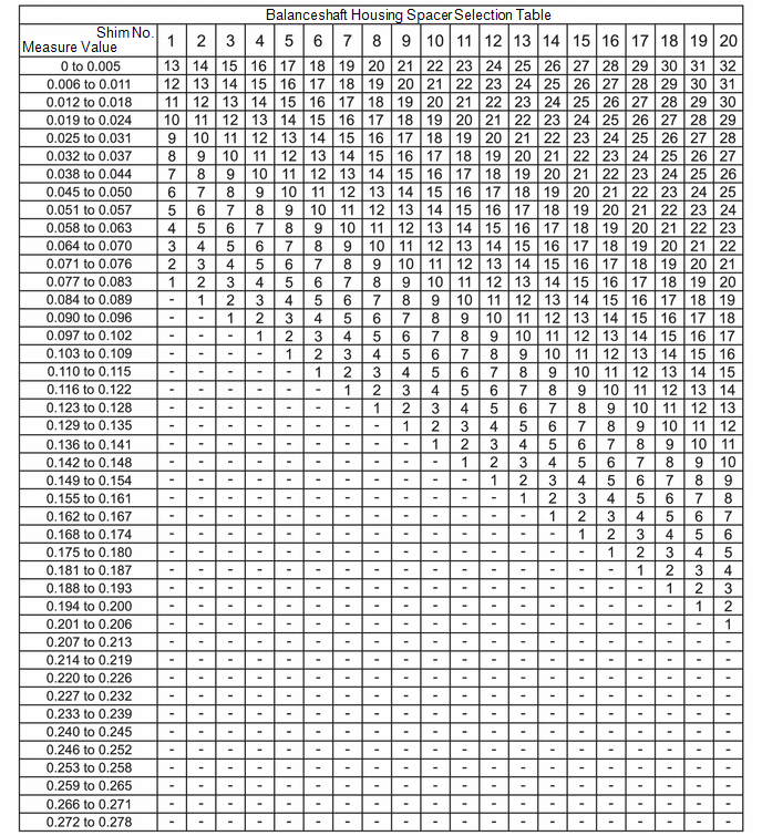
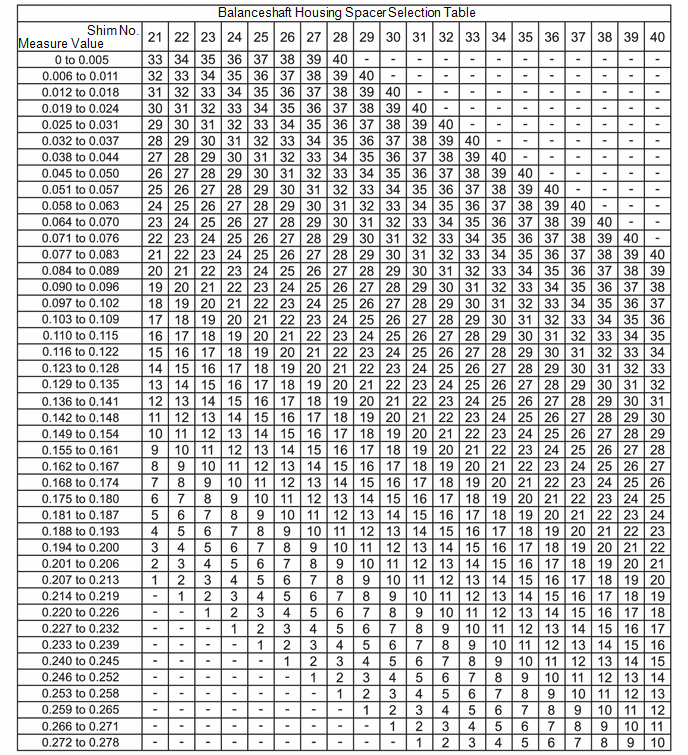
HINT:
- The backlash was 0.114 mm (0.00449 in.) with shim No. 12. Use shim No. 7.
- When adjusting the backlash in the short block condition, select a shim number that is one rank smaller than the specer selecied from the selection table.
- Try to adjust the backlash to the center of the specified values.
(d) Install the balanceshaft housing spacer.
Click here

(e) Install the engine balancer assembly.
Click here

12. INSTALL OIL PAN SUB-ASSEMBLY
(a) Install the new 2 o-ring to the crankshaft bearing cap sub-assembly.
| (b) Apply seal packing in a continuous line as shown in the illustration. Seal Packing: Toyota Genuine Seal Packing Black, Three Bond 1207B or equivalent Standard Seal Packing Dimension:
NOTICE:
|
|
| (c) Temporarily install the oil pan sun-assembly with the 13 bolts.
|
|
| (d) Tighten the 13 bolts in the order shown in the illustration to install the oil pan sub-assembly. Torque: 25 N·m {255 kgf·cm} |
|
| (e) Tighten the 2 bolts. Torque: 46 N·m {469 kgf·cm} |
|
13. INSTALL NO. 2 OIL PAN SUB-ASSEMBLY
Click here

14. CONNECT COMPRESSOR WITH PULLEY ASSEMBLY
(a) Tighten the 2 bolts and connect the compressor with pulley assembly..
Torque:
25 N·m {255 kgf·cm}
15. INSTALL OIL FILTER BRACKET SUB-ASSEMBLY
(a) Install the new 2 o-ring.
(b) Install the bolt, 2 nuts and oil filter bracket sub-assembly to the oil pan sub-assembly.
Torque:
21 N·m {214 kgf·cm}
(c) Install the No. 5 water by-pass hose and slide the 2 clips to secure it.
(d) Install the No. 6 water by-pass hose and slide the 2 clips to secure it.
16. INSTALL FAN AND GENERATOR V BELT
Click here

17. ADD ENGINE COOLANT
Click here

18. ADD ENGINE OIL
Click here

19. INSPECT FOR ENGINE OIL LEAK
Click here

20. INSPECT COOLANT LEAKS
Click here

21. INSTALL NO. 1 ENGINE UNDER COVER ASSEMBLY
Click here

22. INSPECT ENGINE OIL LEVEL
Click here

23. INSPECT ENGINE COOLANT QUALITY
Click here

 Balanceshaft
..
 Camshaft
..
Other information:
Toyota Yaris XP210 (2020-2026) Reapir and Service Manual: Removal
REMOVAL CAUTION / NOTICE / HINT HINT: Use the same procedure for the RH side and LH side. The following procedure is for the LH side. PROCEDURE 1. REMOVE REAR WHEEL Click here 2. REMOVE REAR AXLE SHAFT NUT (a) Using SST and a hammer, release the staked part of the rear axle shaft nut...
Toyota Yaris XP210 (2020-2026) Reapir and Service Manual: License Plate Light Bulb
ComponentsCOMPONENTS ILLUSTRATION *1 LICENSE PLATE LIGHT LENS *2 LICENSE PLATE LIGHT BULB RemovalREMOVAL CAUTION / NOTICE / HINT HINT: Use the same procedure for the RH and LH sides. The procedure listed below is for the LH side. PROCEDURE 1...
Categories
- Manuals Home
- Toyota Yaris Owners Manual
- Toyota Yaris Service Manual
- Fuse Panel Description
- Brake System Control Module "A" System Voltage System Voltage Low (C137BA2)
- To Set Speed
- New on site
- Most important about car
Front Seat Belt Pretensioners
The front seat belt pretensioners are designed to deploy in moderate or severe frontal, near frontal collisions.
In addition, the pretensioners operate when a side collision or a rollover accident is detected. The pretensioners operate differently depending on what types of air bags are equipped. For more details about the seat belt pretensioner operation, refer to the SRS Air Bag Deployment Criteria.