Toyota Yaris: Manifold Absolute Pressure Sensor / On-vehicle Inspection
ON-VEHICLE INSPECTION
PROCEDURE
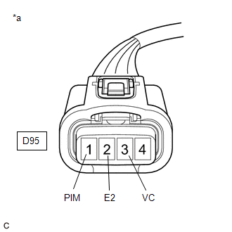
1. INSPECT NO. 1 TURBO PRESSURE SENSOR
(a) Check the terminal voltage.
(1) Disconnect the No. 1 turbo pressure sensor connector.
(2) Turn the ignition switch to ON.
| (3) Measure the voltage according to the value(s) in the table below. Standard Voltage:
If the result is not as specified, repair or replace the wire harness or connector. |
|
(b) Check the turbo pressure.
(1) Connect the GTS to the DLC3.
(2) Turn the ignition switch to ON.
(3) Turn the GTS on.
(4) Enter the following menus: Powertrain / Engine / Data List / Boost Pressure Sensor.
Powertrain > Engine > Data List| Tester Display |
|---|
| Boost Pressure Sensor |
(5) According to the display on the GTS read the Data List.
OK:
The value is approximately equal to atmospheric pressure.
HINT:
- Standard atmospheric pressure is 101 kPa (abs) (758 mmHg (abs)).
- For every 100 m (328 ft.) increase in altitude, pressure drops by 1 kPa (7.5 mmHg). This varies with the weather.
 Components
C..
 Removal
REMOVAL PROCEDURE 1. DISCONNECT ENGINE WIRE (a) Remove the bolt.
(b) Disengage the clamp and disconnect the engine wire. 2. REMOVE NO. 1 TURBO PRESSURE SENSOR (a) Disconnect the No...
Other information:
Toyota Yaris XP210 (2020-2026) Reapir and Service Manual: Precaution
PRECAUTION HANDLING PRECAUTION (a) Always ensure that the ignition switch is off before removing the brake actuator assembly or a sensor unless specifically instructed by the repair manual. (b) When replacing the brake actuator assembly, always replace it with a new one...
Toyota Yaris XP210 (2020-2026) Reapir and Service Manual: Brake Switch "A" Circuit Open (P057113)
DESCRIPTION The skid control ECU (brake actuator assembly) detects the brake operating conditions through a signal transmitted by the stop light switch. The skid control ECU incorporates a circuit to detect an open circuit. This DTC is output when an open circuit is detected in the stop light signal input line...
Categories
- Manuals Home
- Toyota Yaris Owners Manual
- Toyota Yaris Service Manual
- Key Battery Replacement
- Maintenance
- Engine Start Function When Key Battery is Dead
- New on site
- Most important about car
Refueling
Before refueling, close all the doors, windows, and the liftgate/trunk lid, and switch the ignition OFF.
To open the fuel-filler lid, pull the remote fuel-filler lid release.
