Toyota Yaris: Meter / Gauge System / Meter Illumination is Always Dark
DESCRIPTION
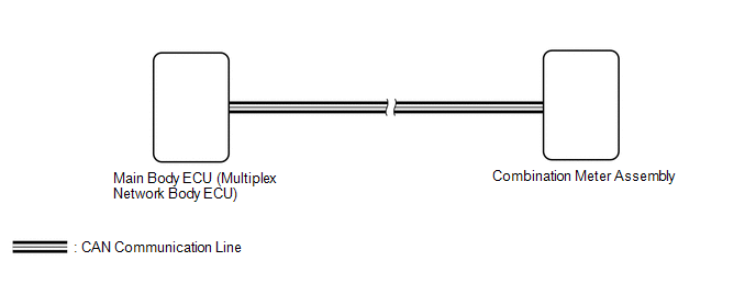
The combination meter assembly receives signals from this circuit to adjust the illumination of the combination meter assembly. The combination meter assembly sets the illumination level based on the user operation of the light control rheostat.
WIRING DIAGRAM
CAUTION / NOTICE / HINT
NOTICE:
-
Before replacing the main body ECU (multiplex network body ECU), refer to Registration.
Click here

- When replacing the combination meter assembly, always replace it with a new one. If a combination meter assembly which was installed to another vehicle is used, the information stored in it will not match the information from the vehicle and a DTC may be stored.
HINT:
- The meter illumination dims when the taillights are turned on.
- Setting the meter illumination level to maximum brightness cancels the above dimming of the meter illumination.
- Setting the meter illumination level to minimum brightness turns off the meter illumination.
-
The automatic light control sensor sensitivity can be customized.
Click here

PROCEDURE
| 1. | CHECK CAN COMMUNICATION SYSTEM |
(a) Check if CAN communication DTCs are output.
Click here

| Result | Proceed to |
|---|---|
| DTCs are not output | A |
| DTCs are output | B |
| B |
 | GO TO CAN COMMUNICATION SYSTEM |
|

| 2. | CHECK FOR DTC (LIGHTING SYSTEM) |
(a) Check if lighting system DTCs are output.
Body Electrical > Main Body > Trouble CodesOK:
DTC B124400 is not output.
| NG |
 | GO TO DTC B124400 |
|

| 3. | CHECK COMBINATION METER ASSEMBLY |
(a) Replace the combination meter assembly with a new one.
Click here

(b) Check the operation.
OK:
The operation of the combination meter assembly returns to normal.
| OK |
 | END (COMBINATION METER ASSEMBLY IS DEFECTIVE) |
| NG |
 | REPLACE MAIN BODY ECU (MULTIPLEX NETWORK BODY ECU) |
 Engine Coolant Temperature Receiver Gauge Malfunction
DESCRIPTION In this circuit, the combination meter assembly receives engine coolant temperature signals from the ECM via CAN communication. The combination meter assembly displays an engine coolant temperature warning based on the data received from the ECM...
 Meter Illumination does not Dim at Night
DESCRIPTION In this circuit, the combination meter assembly receives auto dimmer signals from the main body ECU (multiplex network body ECU) via CAN communication...
Other information:
Toyota Yaris XP210 (2020-2026) Reapir and Service Manual: Components
COMPONENTS ILLUSTRATION *1 REAR DIFFERENTIAL DRAIN PLUG *2 REAR DIFFERENTIAL FILLER PLUG *3 GASKET - - Tightening torque for "Major areas involving basic vehicle performance such as moving/turning/stopping" : N*m (kgf*cm, ft...
Toyota Yaris XP210 (2020-2026) Reapir and Service Manual: VEHICLE CONTROL HISTORY (RoB)
VEHICLE CONTROL HISTORY (RoB) DESCRIPTION (SFI SYSTEM) Vehicle Control History is a function that captures and stores ECU data when triggered by specific vehicle behavior. If the customer states that the engine stalls or will not start, it may be possible to diagnose the cause of the malfunction by checking the vehicle history information and freeze frame data...
Categories
- Manuals Home
- Toyota Yaris Owners Manual
- Toyota Yaris Service Manual
- Removal
- Brake System Control Module "A" System Voltage System Voltage Low (C137BA2)
- Fuel Gauge
- New on site
- Most important about car
Keys

To use the auxiliary key, press the knob and pull out the auxiliary key from the smart key.
