Toyota Yaris: Charging System / Lost Communication with Battery Monitor Module Missing Message (P162B87)
DESCRIPTION
The ECM and battery state sensor assembly each detect reception malfunctions. A battery state sensor assembly reception malfunction detected by the battery state sensor assembly is sent to the ECM via LIN communication. If there is a malfunction in either the ECM or battery state sensor assembly, the ECM determines that there is a LIN communication malfunction and outputs a DTC.
| DTC No. | Detection Item | DTC Detection Condition | Trouble Area | MIL | Note |
|---|---|---|---|---|---|
| P162B87 | Lost Communication with Battery Monitor Module Missing Message | Battery state sensor assembly or ECM communication stops for approximately 17 minutes or more with the ignition switch to ON (1 trip detection logic) |
| Does not come on | SAE Code: P162B |
WIRING DIAGRAM
Refer to the wiring diagram for the P062049.
Click here

CAUTION / NOTICE / HINT
NOTICE:
- Inspect the fuses for circuits related to this system before performing the following inspection procedure.
- Before replacing the ECM, refer to Service Bulletin.
PROCEDURE
| 1. | CHECK BATTERY STATE SENSOR ASSEMBLY INSTALLATION CONDITION |
HINT:
Click here

| NG |
 | INSTALL BATTERY STATE SENSOR ASSEMBLY CORRECTLY |
|
| 2. | CHECK CHARGING SYSTEM |
HINT:
Click here

| NG |
 | REPAIR OR REPLACE CHARGING SYSTEM |
|
| 3. | CHECK HARNESS AND CONNECTOR (ECM - BATTERY STATE SENSOR ASSEMBLY) |
(a) Disconnect the D104 ECM connector.
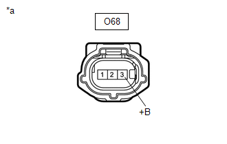
(b) Disconnect the O68 battery state sensor assembly connector.
(c) Disconnect the D53 generator assembly connector.
(d) Measure the resistance according to the value(s) in the table below.
Standard Resistance (Check for Open):
| Tester Connection | Condition | Specified Condition |
|---|---|---|
| D104-62 (LIN) - O68-2 (LIN) | Always | Below 1 Ω |
Standard Resistance (Check for Short):
| Tester Connection | Condition | Specified Condition |
|---|---|---|
| D104-62 (LIN), D53-2 (LIN) or O68-2 (LIN) - Body ground | Ignition switch off (while LIN communication stopped) | 10 kΩ or higher |
| NG |
 | REPAIR OR REPLACE HARNESS OR CONNECTOR |
|
| 4. | CHECK HARNESS AND CONNECTOR (POWER SOURCE CIRCUIT) |
(a) Check that the battery state sensor assembly connector is securely connected.
OK:
The connector is securely connected.
| (b) Disconnect the O68 battery state sensor assembly connector. |
|
(c) Check the connector case and terminals for deformation or corrosion.
OK:
No deformation or corrosion.
(d) Measure the voltage according to the value(s) in the table below.
Standard Voltage:
| Tester Connection | Condition | Specified Condition |
|---|---|---|
| O68-3 (+B) - Body ground | Always | 11 to 14 V |
| NG |
 | REPAIR OR REPLACE HARNESS OR CONNECTOR |
|
| 5. | CLEAR DTC |
(a) Check for DTCs using the GTS, and then write them down.
Powertrain > Engine > Trouble Codes(b) Clear the DTCs.
Powertrain > Engine > Clear DTCs
|
| 6. | READ OUTPUT DTC |
(a) Start the engine and wait 17 minutes or more.
(b) Using the GTS, read the DTCs.
Powertrain > Engine > Trouble Codes| Result | Proceed to |
|---|---|
| Only P162B87 is output | A |
| P161A87 and P162B87 are output | B |
| DTCs are not output | C |
| A |
 | REPLACE BATTERY STATE SENSOR ASSEMBLY |
| B |
 | REPLACE ECM |
| C |
 | CHECK FOR INTERMITTENT PROBLEMS |
 Lost Communication with Alternator Missing Message (P161A87)
DESCRIPTION The ECM communicates with the generator assembly via LIN communication. If a LIN communication error is detected, the ECM stores this DTC. DTC No...
 Charging Failure
PROCEDURE 1. CHECK GENERATOR PULLEY WITH CLUTCH (ON-VEHICLE INSPECTION) (a) Start the engine and visually check that the generator rotor assembly (fan) in the generator assembly is operating...
Other information:
Toyota Yaris XP210 (2020-2026) Reapir and Service Manual: Front Passenger Side Power Window does not Operate with Front Passenger Side Power Window Switch
DESCRIPTION When the ignition switch is ON, the power window regulator motor assembly (for front passenger door) is operated by the power window regulator switch assembly. The power window regulator motor assembly (for front passenger door) has motor, regulator, and ECU functions...
Toyota Yaris XP210 (2020-2026) Reapir and Service Manual: On-vehicle Inspection
ON-VEHICLE INSPECTION PROCEDURE 1. CHECK AUXILIARY BATTERY CONDITION NOTICE: If the auxiliary battery is weak or if the engine is difficult to start, recharge the auxiliary battery and perform inspections again before returning the vehicle to the customer...
Categories
- Manuals Home
- Toyota Yaris Owners Manual
- Toyota Yaris Service Manual
- How to use USB mode
- Key Battery Replacement
- Immobilizer System
- New on site
- Most important about car
Fuel-Filler Lid and Cap
WARNING
When removing the fuel-filler cap, loosen the cap slightly and wait for any hissing to stop, then remove it
Fuel spray is dangerous. Fuel can burn skin and eyes and cause illness if ingested. Fuel spray is released when there is pressure in the fuel tank and the fuel-filler cap is removed too quickly.


