Toyota Yaris: Charging System / On-vehicle Inspection
ON-VEHICLE INSPECTION
PROCEDURE
1. CHECK AUXILIARY BATTERY CONDITION
NOTICE:
If the auxiliary battery is weak or if the engine is difficult to start, recharge the auxiliary battery and perform inspections again before returning the vehicle to the customer.
(a) Check the auxiliary battery for damage or deformation. If severe damage, deformation or leakage is found, replace the auxiliary battery.
(b) Check the electrolyte level in each cell.
-
If the electrolyte level is below the lower line, add distilled water to each cell. Then, recharge the auxiliary battery and check the electrolyte specific gravity.
Standard Specific Gravity:
1.25 or higher at 20°C (68°F)
-
If the electrolyte level is above the lower line, check the auxiliary battery voltage while cranking the engine. If the auxiliary battery voltage is less than 9.6 V, recharge or replace the auxiliary battery.
HINT:
Before checking the auxiliary battery voltage, turn off all the electrical systems (headlights, blower motor, rear window defogger, etc.).
(c) Check the voltage.
(1) Turn the ignition switch off and turn on the headlights for 20 to 30 seconds. This will remove the surface charge from the auxiliary battery.
(2) Measure the auxiliary battery voltage according to the value(s) in the table below.
Standard Voltage:
| Tester Connection | Condition | Specified Condition |
|---|---|---|
| Positive (+) terminal - Negative (-) terminal | 20°C (68°F) | 12.3 V or higher |
If the result is not as specified, recharge or replace the auxiliary battery.
2. CHECK BATTERY TERMINAL, BATTERY STATE SENSOR ASSEMBLY
(a) Check whether the battery state sensor assembly is deformed or cracked.
Torque:
Positive (+) Battery Terminal :
5.4 N·m {55 kgf·cm, 48 in·lbf}
Negative (-) Battery Terminal (Battery State Sensor Assembly) :
5.4 N·m {55 kgf·cm, 48 in·lbf}
(b) Check that the battery terminals are not loose or corroded.
If a terminal is loose or corroded, tighten or clean the terminal.
Torque:
Positive (+) Battery Terminal :
5.4 N·m {55 kgf·cm, 48 in·lbf}
Negative (-) Battery Terminal (Battery State Sensor Assembly) :
5.4 N·m {55 kgf·cm, 48 in·lbf}
3. CHECK FUSES
(a) Measure the resistance of each fuse for the charging system.
HINT:
The fuses shown in System Diagram are related to the charging system.
Standard Resistance:
Below 1 Ω
- If the result is not as specified, replace the fuse.
4. INSPECT FAN AND GENERATOR V BELT
Click here

5. INSPECT GENERATOR ASSEMBLY WIRING
(a) Visually check the generator assembly wiring.
(1) Check that the wiring is in good condition.
6. CHECK FOR ABNORMAL NOISE
(a) Check for abnormal noises from the generator assembly.
(1) Check that no abnormal noises are heard from the generator assembly while the engine is running.
If noise occurs, refer to Problem Symptoms Table.
Click here

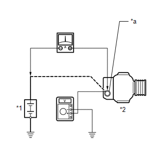
7. INSPECT CHARGING CIRCUIT WITHOUT LOAD
| (a) Connect a voltmeter and an ammeter to the charging circuit as follows. HINT: If a battery/generator assembly tester is available, connect the tester to the charging circuit in accordance with the manufacturer's instructions. (1) Disconnect the wire from terminal B of the generator assembly and connect it to the negative (-) lead of the ammeter. (2) Connect the ammeter positive (+) lead to terminal B of the generator assembly. (3) Connect the voltmeter positive (+) lead to the positive (+) terminal of the auxiliary battery. (4) Ground the voltmeter negative (-) lead. |
|
(b) Check the charging circuit.
(1) Maintain the engine speed at 2000 rpm and check the readings on the ammeter and voltmeter.
Standard Current:
10 A or less
Standard Voltage:
13.2 to 14.8 V
If the result is not as specified, repair or replace the generator assembly.
8. INSPECT CHARGING CIRCUIT WITH LOAD
(a) With the engine running at 2000 rpm, turn the high beam headlights on and turn the heater blower switch to the "HI" position.
(b) Check the reading on the ammeter.
Standard Current:
30 A or higher
If the result is not as specified, repair or replace the generator assembly.
HINT:
If the auxiliary battery is fully charged, the reading will sometimes be less than the standard current. In this case, add more electrical load (operate the wipers, rear window defogger, etc.) and check the reading on the ammeter again.
9. INSPECT CHARGING SYSTEM
(a) Check the harness and connector.
(1) Disconnect the D104 ECM connector.
(2) Disconnect the D53 generator assembly connector.
(3) Disconnect the O68 battery state sensor assembly connector.
(4) Measure the resistance according to the value(s) in the table below.
Standard Resistance:
| Tester Connection | Condition | Specified Condition |
|---|---|---|
| D104-62 (LIN) - D53-2 (LIN) | Always | Below 1 Ω |
| D104-62 (LIN) or D53-2 (LIN) - Body ground | Ignition switch off (while LIN communication stopped) | 10 kΩ or higher |
| D104-62 (LIN) - O68-2 (LIN) | Always | Below 1 Ω |
| D104-62 (LIN) or O68-2 (LIN) - Body ground | Ignition switch off (while LIN communication stopped) | 10 kΩ or higher |
If the result is not as specified, repair or replace the harness or connector.

 Vehicle Control History
VEHICLE CONTROL HISTORY CHECK VEHICLE CONTROL HISTORY (a) Connect the GTS to the DLC3. (b) Turn the ignition switch to ON. (c) Turn the GTS on. (d) Enter the following menus: Powertrain / Engine / Utility / Vehicle Control History (RoB)...
Other information:
Toyota Yaris XP210 (2020-2026) Reapir and Service Manual: Dtc Check / Clear
DTC CHECK / CLEAR DTC CHECK (a) Turn the ignition switch to ON, and wait for at least 60 seconds. (b) Check for DTCs by following the prompts on the GTS screen. Body Electrical > SRS Airbag > Trouble Codes HINT: Refer to the GTS operator's manual for further details...
Toyota Yaris XP210 (2020-2026) Reapir and Service Manual: Removal
REMOVAL CAUTION / NOTICE / HINT The necessary procedures (adjustment, calibration, initialization or registration) that must be performed after parts are removed and installed, or replaced during fuel injector assembly removal/installation are shown below...
Categories
- Manuals Home
- Toyota Yaris Owners Manual
- Toyota Yaris Service Manual
- To Set Speed
- How to use USB mode
- Auto Lock/Unlock Function
- New on site
- Most important about car
Supplemental Restraint System (SRS) Precautions
The front and side supplemental restraint systems (SRS) include different types of air bags. Please verify the different types of air bags which are equipped on your vehicle by locating the “SRS AIRBAG” location indicators. These indicators are visible in the area where the air bags are installed.
The air bags are installed in the following locations:
The steering wheel hub (driver air bag) The front passenger dashboard (front passenger air bag) The outboard sides of the front seatbacks (side air bags) The front and rear window pillars, and the roof edge along both sides (curtain air bags)