Toyota Yaris: Power Window Control System / Front Passenger Side Power Window does not Operate with Front Passenger Side Power Window Switch
DESCRIPTION
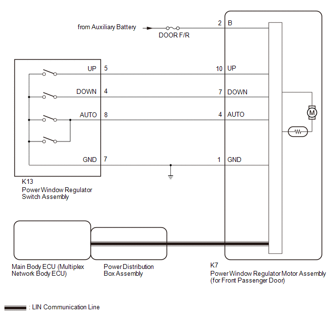
When the ignition switch is ON, the power window regulator motor assembly (for front passenger door) is operated by the power window regulator switch assembly. The power window regulator motor assembly (for front passenger door) has motor, regulator, and ECU functions.
WIRING DIAGRAM
CAUTION / NOTICE / HINT
NOTICE:
-
The power window control system uses the LIN communication system. Inspect the communication function by following How to Proceed with Troubleshooting. Troubleshoot the power window control system after confirming that the communication system is functioning properly.
Click here
.gif)
-
If the power window regulator motor assembly (for front passenger door) has been replaced with a new one, initialize the power window control system.
Click here
- Check that the window lock switch is off before performing the following procedure.
- Inspect the fuses for circuits related to this system before performing the following procedure.
-
If the main body ECU (multiplex network body ECU) is replaced, refer to the Registration.
Click here
PROCEDURE
| 1. | READ VALUE USING GTS (MAIN BODY) |
(a) Read the Data List according to the display on the GTS.
Body Electrical > Main Body > Data List| Tester Display | Measurement Item | Range | Normal Condition | Diagnostic Note |
|---|---|---|---|---|
| Communication P-Door Motor | Connection status between power window regulator motor assembly (for front passenger door) and main body ECU (multiplex network body ECU) | STOP or OK | STOP: Communication stopped OK: Normal communication | - |
| Tester Display |
|---|
| Communication P-Door Motor |
OK:
OK is displayed for each Data List item above.
| NG |
.gif) | GO TO LIN COMMUNICATION SYSTEM (Proceed to How to Proceed with Troubleshooting) |
|
.gif)
| 2. | READ VALUE USING GTS (P-DOOR MOTOR) |
(a) Read the Data List according to the display on the GTS.
Body Electrical > P-Door Motor > Data List| Tester Display | Measurement Item | Range | Normal Condition | Diagnostic Note |
|---|---|---|---|---|
| P Door P/W Up SW | Front passenger door power window manual up switch signal | OFF or ON | OFF: Front passenger door power window manual up switch not being operated ON: Front passenger door power window manual up switch being operated | - |
| P Door P/W Down SW | Front passenger door power window manual down switch signal | OFF or ON | OFF: Front passenger door power window manual down switch not being operated ON: Front passenger door power window manual down switch being operated | - |
| Tester Display |
|---|
| P Door P/W Up SW |
| P Door P/W Down SW |
OK:
On the GTS screen, ON or OFF is displayed accordingly.
| NG |
| GO TO STEP 4 |
|
| 3. | PERFORM ACTIVE TEST USING GTS (P-DOOR MOTOR) |
(a) Perform the Active Test according to the display on the GTS.
CAUTION:
Be careful to avoid injuries as this test causes vehicle parts to move. During the Active Test, the jam protection function will not operate.
Body Electrical > P-Door Motor > Active Test| Tester Display | Measurement Item | Control Range | Diagnostic Note |
|---|---|---|---|
| Power Window | Power window | OFF / DOWN / UP | - |
| Tester Display |
|---|
| Power Window |
OK:
Front passenger door power window operates normally.
| OK |
| REPLACE MAIN BODY ECU (MULTIPLEX NETWORK BODY ECU) |
| NG |
| REPLACE POWER WINDOW REGULATOR MOTOR ASSEMBLY (for Front Passenger Door) |
| 4. | INSPECT POWER WINDOW REGULATOR SWITCH ASSEMBLY |
Click here
| NG |
| REPLACE POWER WINDOW REGULATOR SWITCH ASSEMBLY |
|
| 5. | CHECK HARNESS AND CONNECTOR (POWER WINDOW REGULATOR SWITCH ASSEMBLY - POWER WINDOW REGULATOR MOTOR ASSEMBLY (for Front Passenger Door)) |
(a) Disconnect the K7 power window regulator motor assembly (for front passenger door) connector.
(b) Measure the resistance according to the value(s) in the table below.
Standard Resistance:
| Tester Connection | Condition | Specified Condition |
|---|---|---|
| K13-5 (UP) - K7-10 (UP) | Always | Below 1 Ω |
| K13-5 (UP) or K7-10 (UP) - Body ground | Always | 10 kΩ or higher |
| K13-4 (DOWN) - K7-7 (DOWN) | Always | Below 1 Ω |
| K13-4 (DOWN) or K7-7 (DOWN) - Body ground | Always | 10 kΩ or higher |
| OK |
| REPLACE POWER WINDOW REGULATOR MOTOR ASSEMBLY (for Front Passenger Door) |
| NG |
| REPAIR OR REPLACE HARNESS OR CONNECTOR |
 Driver Side Power Window does not Operate with Power Window Master Switch
DESCRIPTION When the ignition switch is ON, the power window regulator motor assembly (for driver door) is operated by the multiplex network master switch assembly...
 Driver Side Power Window Auto Up / Down Function does not Operate with Power Window Master Switch
DESCRIPTION If the manual up and down functions operate normally but the auto up and down functions do not, the power window control system may be in fail-safe mode...
Other information:
Toyota Yaris XP210 (2020-2025) Owner's Manual: Installation on rear outboard seats
First, adjust the front seat to allow clearance between the child-restraint system and the front seat. Make sure the seatback is securely latched by pushing it back until it is fully locked. Expand the open seams on the rear of the seat bottom slightly to verify the locations of the LATCH lower anchors...
Toyota Yaris XP210 (2020-2025) Reapir and Service Manual: All Door Entry Lock/Unlock Functions do not Operate, but Wireless Functions Operate
DESCRIPTION When the wireless operation can be used to lock and unlock the doors, communication between the smart door control receiver assembly and certification ECU (smart key ECU assembly) is normal. If the entry lock and unlock functions do not operate, the entry cancel function may be set through the customize function, there may be communication problems between the electrical key transmitter sub-assembly and vehicle, or there may be wave interference...
Categories
- Manuals Home
- Toyota Yaris Owners Manual
- Toyota Yaris Service Manual
- Maintenance
- Headlights
- Diagnostic Trouble Code Chart
- New on site
- Most important about car
Supplemental Restraint System (SRS) Precautions
The front and side supplemental restraint systems (SRS) include different types of air bags. Please verify the different types of air bags which are equipped on your vehicle by locating the “SRS AIRBAG” location indicators. These indicators are visible in the area where the air bags are installed.
The air bags are installed in the following locations:
The steering wheel hub (driver air bag) The front passenger dashboard (front passenger air bag) The outboard sides of the front seatbacks (side air bags) The front and rear window pillars, and the roof edge along both sides (curtain air bags)