Toyota Yaris: Installing Child-Restraint Systems / Installation on rear outboard seats
- First, adjust the front seat to allow clearance between the child-restraint system and the front seat.
- Make sure the seatback is securely latched by pushing it back until it is fully locked.
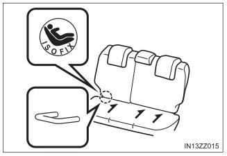
- Expand the open seams on the
rear of the seat bottom slightly
to verify the locations of the
LATCH lower anchors.
The markings above the LATCH lower anchors indicate the locations of the LATCH lower anchors for the attachment of a child-restraint system.
- Remove the head restraint. Refer to Head Restraints.
- Secure the child-restraint system using BOTH LATCH lower anchors, following the child-restraint system manufacturer’s instruction. Pull on the child-restraint to be sure both anchors are engaged.
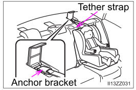
- If your child-restraint system came equipped with a tether, that means it is very important to properly secure the tether for child safety. Please carefully follow the child-restraint system manufacturer’s instructions when installing tethers.
WARNING
Use the tether and tether anchor only for a child-restraint system
Using the tether or tether anchor to secure anything but a child-restraint system is dangerous. This could weaken or damage the tether or tether anchor and result in injury.
Always remove the head restraint and install child-restraint system
Installing a child-restraint system without removing the head restraint is dangerous. The child-restraint system cannot be installed correctly which may result in death or injury to the child in a collision.
4-Door
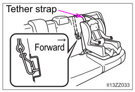
5-Door
WARNING
Always attach the tether strap to the correct tether anchor position
Attaching the tether strap to the incorrect tether anchor position is dangerous. In a collision, the tether strap could come off and loosen the childrestraint system. If the child-restraint system moves it could result in death or injury to the child.
Always install the head restraint and adjust it to the appropriate position after removing the child-restraint system
Driving with the head restraint removed is dangerous as impact to the occupant’s head cannot be prevented during emergency braking or in a collision, which could result in a serious accident, injury or death. Refer to Head Restraints.
 Using LATCH Lower Anchor
Your Toyota is equipped with LATCH lower anchors for attachment of
specially designed LATCH child-restraint systems in the rear seats.
Both anchors must be used, otherwise the seat will bounce around
and put the child in danger...
 Installation on rear center seat
The LATCH lower anchors at the center of the rear seat are much further apart
than the sets of LATCH lower anchors for child-restraint
system installation at other seating positions...
Other information:
Toyota Yaris XP210 (2020-2026) Reapir and Service Manual: Right Front Wheel Speed Sensor Circuit Short to Ground or Open (C050614)
DESCRIPTION Refer to DTC C05061F. Click here DTC No. Detection Item DTC Detection Condition Trouble Area DTC Output from C050614 Right Front Wheel Speed Sensor Circuit Short to Ground or Open An open in the speed sensor signal circuit continues for 0...
Toyota Yaris XP210 (2020-2026) Reapir and Service Manual: Diagnostic Trouble Code Chart
D..
Categories
- Manuals Home
- Toyota Yaris Owners Manual
- Toyota Yaris Service Manual
- Headlights
- Fuel Gauge
- Fuse Panel Description
- New on site
- Most important about car
Keys

To use the auxiliary key, press the knob and pull out the auxiliary key from the smart key.
