Toyota Yaris: Clutch Master Cylinder / Installation
INSTALLATION
PROCEDURE
1. INSTALL CLUTCH MASTER CYLINDER ASSEMBLY
(a) Install a new clutch master cylinder gasket to the clutch master cylinder assembly.
(b) Install the clutch master cylinder assembly to the vehicle body with the 2 nuts.
Torque:
12.7 N·m {130 kgf·cm, 9 ft·lbf}
2. INSTALL CLUTCH MASTER CYLINDER PUSH ROD CLEVIS WITH HOLE PIN
Click here

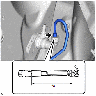
3. CONNECT CLUTCH MASTER CYLINDER TO FLEXIBLE HOSE TUBE
| (a) Using a 10 mm union nut wrench, connect the clutch master cylinder to flexible hose tube to the clutch master cylinder assembly. Torque: Specified Tightening Torque : 15.2 N·m {155 kgf·cm, 11 ft·lbf} NOTICE:
HINT:
|
|

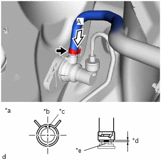
4. CONNECT NO. 1 CLUTCH RESERVOIR HOSE
| (a) Connect the No. 1 clutch reservoir hose to the clutch master cylinder assembly and slide the hose clip to secure it. NOTICE:
|
|
5. INSTALL BRAKE BOOSTER ASSEMBLY
Click here

6. BLEED CLUTCH LINE
Click here

7. INSPECT FOR BRAKE FLUID LEAK
8. INSPECT BRAKE FLUID LEVEL IN RESERVOIR
Click here

9. INSPECT CLUTCH PEDAL
Click here

 Removal
REMOVAL CAUTION / NOTICE / HINT HINT: When the cable is disconnected / reconnected to the auxiliary battery terminal, systems temporarily stop operating...
 Clutch Pedal
..
Other information:
Toyota Yaris XP210 (2020-2026) Reapir and Service Manual: Installation
INSTALLATION CAUTION / NOTICE / HINT HINT: Use the same procedure for the RH side and LH side. The following procedure is for the LH side. PROCEDURE 1. INSTALL FRONT AXLE HUB SUB-ASSEMBLY (a) Secure the steering knuckle between aluminum plates in a vise...
Toyota Yaris XP210 (2020-2026) Reapir and Service Manual: Components
C..
Categories
- Manuals Home
- Toyota Yaris Owners Manual
- Toyota Yaris Service Manual
- Brake System Control Module "A" System Voltage System Voltage Low (C137BA2)
- Auto Lock/Unlock Function
- Engine Start Function When Key Battery is Dead
- New on site
- Most important about car
Fuel Gauge
The fuel gauge shows approximately how much fuel is remaining in the tank when the ignition is switched ON. We recommend keeping the tank over 1/4 full.
