Toyota Yaris: G16e-gts Auxiliary Battery / Installation
INSTALLATION
PROCEDURE
1. INSTALL AUXILIARY BATTERY
(a) Install the auxiliary battery.
(b) Install the battery clamp sub-assembly to the body with the nut and bolt.
Torque:
Bolt :
11.5 N·m {117 kgf·cm, 8 ft·lbf}
Nut :
5.4 N·m {55 kgf·cm, 48 in·lbf}
(c) Connect the battery hose to the auxiliary battery.
(d) Engage the spring assembly as shown in the illustration.
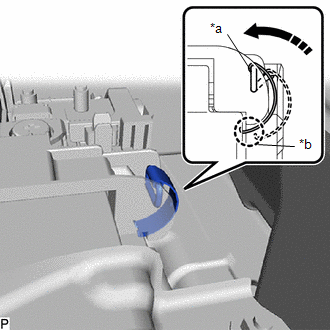
| *a | Locked Position |
| *b | Engage here |
 | Install in this Direction |
(e) Connect the cable to the positive (+) auxiliary battery terminal and tighten the nut.
Torque:
5.4 N·m {55 kgf·cm, 48 in·lbf}
(f) Engage the claw and install the fusible link cover.
2. CONNECT CABLE FROM NEGATIVE AUXILIARY BATTERY TERMINAL
(a) Connect the cable to the negative (-) auxiliary battery terminal and tighten the nut.
Torque:
5.4 N·m {55 kgf·cm, 48 in·lbf}
3. INSTALL DECK BOARD ASSEMBLY
Click here

4. INITIALIZATION AFTER RECONNECTING AUXILIARY BATTERY TERMINAL
HINT:
When disconnecting and reconnecting theauxiliary battery, there is an automatic learning function that completes learning when the respective system is used.
Click here

 Removal
REMOVAL CAUTION / NOTICE / HINT HINT: When the cable is disconnected / reconnected to the auxiliary battery terminal, systems temporarily stop operating...

Other information:
Toyota Yaris XP210 (2020-2026) Reapir and Service Manual: Inspection
INSPECTION PROCEDURE 1. INSPECT CAMSHAFT TIMING OIL CONTROL SOLENOID ASSEMBLY (for Intake Side) (a) Check the resistance. (1) Measure the resistance according to the value(s) in the table below. Standard Resistance: Tester Connection Condition Specified Condition D92-1 - D92-2 0 °C (32 °F) 6...
Toyota Yaris XP210 (2020-2026) Reapir and Service Manual: Camshaft Position Sensor "A" Bank 1 or Single Sensor Circuit Short to Ground (P034011,P034015)
DESCRIPTION The camshaft position sensor (for intake camshaft) (VV1 signal) consists of a magnet and MRE (Magneto-Resistive Element). The intake camshaft has a timing rotor for the camshaft position sensor. When the intake camshaft rotates, changes occur in the air gaps between the timing rotor and MRE, which affects the magnetic field...
Categories
- Manuals Home
- Toyota Yaris Owners Manual
- Toyota Yaris Service Manual
- Fuse Panel Description
- Engine & Hybrid System
- Auto Lock/Unlock Function
- New on site
- Most important about car
Fuel-Filler Lid and Cap
WARNING
When removing the fuel-filler cap, loosen the cap slightly and wait for any hissing to stop, then remove it
Fuel spray is dangerous. Fuel can burn skin and eyes and cause illness if ingested. Fuel spray is released when there is pressure in the fuel tank and the fuel-filler cap is removed too quickly.