Toyota Yaris: G16e-gts Auxiliary Battery / Removal
REMOVAL
CAUTION / NOTICE / HINT
HINT:
When the cable is disconnected / reconnected to the auxiliary battery terminal, systems temporarily stop operating. However, each system has a function that completes learning the first time the system is used.
-
Learning completes when vehicle is driven
Effect/Inoperative Function When Necessary Procedures are not Performed
Necessary Procedures
Link
Lane tracing assist system
Drive the vehicle straight ahead at 35 km/h (22 mph) or more for 5 second or more.

Pre-collision system
Stop and start system
Drive the vehicle until stop and start control is permitted (approximately 5 to 60 minutes)

-
Learning completes when vehicle is operated normally
Effect/Inoperative Function When Necessary Procedures are not Performed
Necessary Procedures
Link
Power door lock control system
- Back door opener
Perform door unlock operation with door control switch or electrical key transmitter sub-assembly switch.

Air conditioning system
After the ignition switch is turned to ON, the servo motor standard position is recognized.
-
PROCEDURE
1. PRECAUTION
NOTICE:
-
After turning the ignition switch off, waiting time may be required before disconnecting the cable from the negative (-) auxiliary battery terminal.
Click here

- When replacing the auxiliary battery, use a new auxiliary battery of the same dimensions and same capacity or more from the same class at a 20-hour rate.
2. REMOVE DECK BOARD ASSEMBLY
Click here

3. DISCONNECT CABLE FROM NEGATIVE AUXILIARY BATTERY TERMINAL
| (a) Loosen the nut, and disconnect the cable from the negative (-) auxiliary battery terminal. |
|
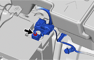
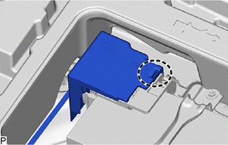
4. REMOVE AUXILIARY BATTERY
| (a) Disengage the claw to remove the fusible link cover. |
|
(b) Loosen the nut.
(c) Disengage the spring assembly and disconnect the cable from the positive (+) auxiliary battery terminal.
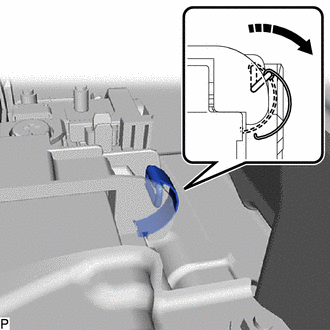
 | Remove in this Direction |
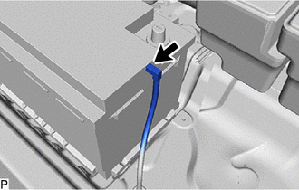
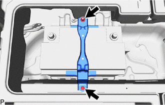
| (d) Disconnect the battery hose from the auxiliary battery. |
|
| (e) Remove the nut, bolt and battery clamp sub-assembly from the body. |
|
(f) Remove the auxiliary battery.
 Components
COMPONENTS ILLUSTRATION
*1 DECK BOARD ASSEMBLY *2 FUSIBLE LINK COVER *3 POSITIVE AUXILIARY BATTERY TERMINAL *4 BATTERY CLAMP SUB-ASSEMBLY *5 NEGATIVE AUXILIARY BATTERY TERMINAL *6 BATTERY HOSE *7 AUXILIARY BATTERY - -
Tightening torque for "Major areas involving basic vehicle performance such as moving/turning/stopping": N*m (kgf*cm, ft...
 Installation
INSTALLATION PROCEDURE 1. INSTALL AUXILIARY BATTERY (a) Install the auxiliary battery. (b) Install the battery clamp sub-assembly to the body with the nut and bolt...
Other information:
Toyota Yaris XP210 (2020-2026) Reapir and Service Manual: Fuel Rail / System Pressure - Too High (P008800)
DESCRIPTION Refer to DTC P008700. Click here DTC No. Detection Item DTC Detection Condition Trouble Area MIL Note P008800 Fuel Rail / System Pressure - Too High Although the ECM is requesting the fuel pump assembly (for high pressure side) to open the spill control valve, fuel pressure increases 3 MPa (30...
Toyota Yaris XP210 (2020-2026) Reapir and Service Manual: Diagnostic Trouble Code Chart
D..
Categories
- Manuals Home
- Toyota Yaris Owners Manual
- Toyota Yaris Service Manual
- Headlights
- How to connect USB port/Auxiliary jack
- Power Integration No.1 System Missing Message (B235287,B235587,B235787-B235987)
- New on site
- Most important about car
Key Suspend Function
If a key is left in the vehicle, the functions of the key left in the vehicle are temporarily suspended to prevent theft of the vehicle.
To restore the functions, press the unlock button on the functions-suspended key in the vehicle.