Toyota Yaris: Rear Disc Brake Pad / Installation
INSTALLATION
CAUTION / NOTICE / HINT
HINT:
- Use the same procedure for the RH side and LH side.
- The following procedure is for the LH side.
PROCEDURE
1. INSTALL REAR DISC BRAKE ANTI SQUEAL SHIM KIT
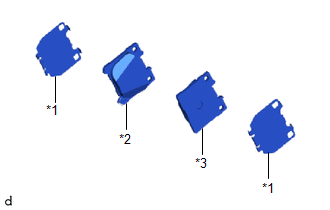
| (a) Install the 2 rear disc brake anti-squeal shims to each rear disc brake pad. NOTICE: When replacing the rear disc brake pads with new ones, make sure to replace the rear disc brake anti-squeal shim kit at the same time. |
|
2. INSTALL REAR DISC BRAKE PAD
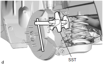
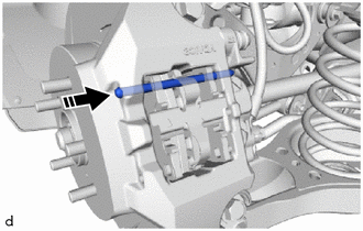
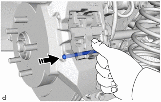
| (a) Using SST, push in the rear disc brake piston. SST: 09719-77010 NOTICE:
|
|
| (b) Install the 2 rear disc brake pads to the rear disc brake cylinder assembly. NOTICE: The rear disc brake pad with the pad wear indicator plate must be installed to the inner lower side position. |
|
3. TEMPORARILY INSTALL REAR DISC BRAKE ANTI-RATTLE SPRING
| (a) Temporarily install the rear disc brake anti-rattle spring to the rear disc brake pads. NOTICE:
|
|
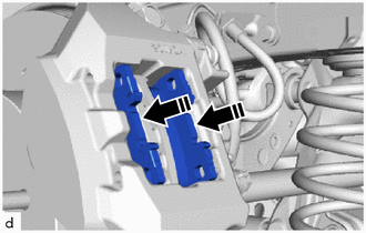
4. INSTALL REAR DISC BRAKE ANTI-RATTLE PIN
| (a) Install the rear disc brake anti-rattle pin (upper side) and set the rear disc brake anti-rattle spring to the rear disc brake pads. NOTICE: Set the rear disc brake anti-rattle spring so that it does not overlap and ride up onto the rear disc brake cylinder assembly. |
|
| (b) While pressing the rear disc brake anti-rattle spring, install the rear disc brake anti-rattle pin (lower side). |
|
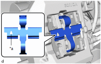
5. INSTALL REAR DISC BRAKE PIN HOLD CLIP
(a) Install the rear disc brake pin hold clip to the 2 rear disc brake anti-rattle pins and engage the hook to the rear disc brake cylinder assembly.
6. INSPECT BRAKE FLUID LEVEL IN RESERVOIR
Click here

NOTICE:
After replacing the rear disc brake pads, the clearance between the rear disc brake pads and the rear disc will be large, so depress the brake pedal several times to adjust the clearance before inspecting the brake fluid level.
7. INSTALL REAR WHEEL
Click here

 Removal
REMOVAL CAUTION / NOTICE / HINT NOTICE: After replacing the rear disc brake pads, the brake pedal may feel soft due to clearance between the rear disc brake pads and rear disc...
 Tire And Wheel
ComponentsCOMPONENTS ILLUSTRATION
*1 WHEEL ASSEMBLY *2 AXLE HUB NUT
Tightening torque for "Major areas involving basic vehicle performance such as moving/turning/stopping" : N*m (kgf*cm, ft...
Other information:
Toyota Yaris XP210 (2020-2026) Reapir and Service Manual: Components
COMPONENTS ILLUSTRATION *A for Driver Side *B for Front Passenger Side *1 FRONT SEAT VERTICAL ADJUSTER HANDLE *2 NO.1 RECLINING HINGE COVER *3 RECLINING ADJUSTER RELEASE HANDLE *4 SEAT ADJUSTER COVER CAP *5 FRONT SEAT CUSHION SHIELD *6 FRONT SEAT INNER CUSHION SHIELD ILLUSTRATION *1 SEPARATE TYPE FRONT SEATBACK ASSEMBLY - - Tightening torque for "Major areas involving basic vehicle performance such as moving/turning/stopping" : N*m (kgf*cm, ft...
Toyota Yaris XP210 (2020-2026) Reapir and Service Manual: Id Code Box
ComponentsCOMPONENTS ILLUSTRATION *1 ID CODE BOX (IMMOBILISER CODE ECU) - - RemovalREMOVAL CAUTION / NOTICE / HINT The necessary procedures (adjustment, calibration, initialization, or registration) that must be performed after parts are removed, installed, or replaced during the ID code box (immobiliser code ECU) removal/installation are shown below...
Categories
- Manuals Home
- Toyota Yaris Owners Manual
- Toyota Yaris Service Manual
- Fuse Panel Description
- Opening and Closing the Liftgate/Trunk Lid
- Key Battery Replacement
- New on site
- Most important about car
Fuel Gauge
The fuel gauge shows approximately how much fuel is remaining in the tank when the ignition is switched ON. We recommend keeping the tank over 1/4 full.
