Toyota Yaris: Maintenance / Tire And Wheel
Components
COMPONENTS
ILLUSTRATION
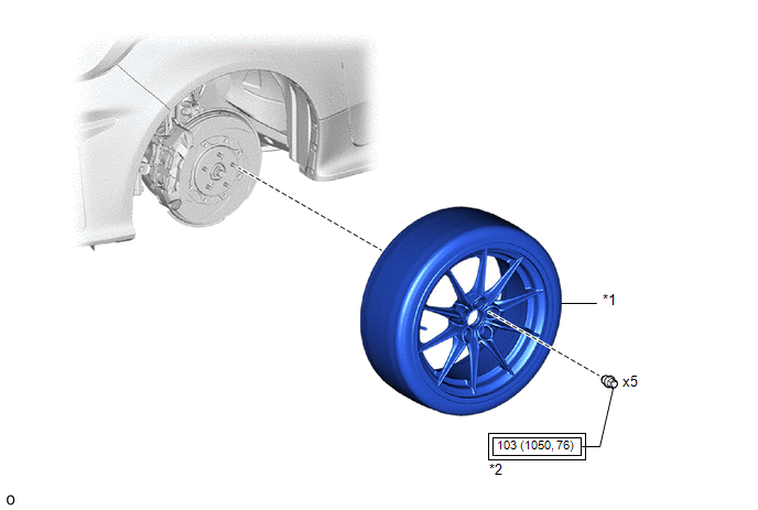
| *1 | WHEEL ASSEMBLY | *2 | AXLE HUB NUT |
 | Tightening torque for "Major areas involving basic vehicle performance such as moving/turning/stopping" : N*m (kgf*cm, ft.*lbf) | - | - |
Removal
REMOVAL
PROCEDURE
1. REMOVE WHEEL ASSEMBLY
(a) Loosen the axle hub nuts approximately 90°.
(b) Lift up the vehicle and remove the axle hub nuts and wheel assembly.
Installation
INSTALLATION
PROCEDURE
1. INSTALL WHEEL ASSEMBLY
NOTICE:
- Only use axle hub nuts that are compatible with the wheel. If incompatible axle hub nuts are used, the contact surface of the wheel and axle hub nut may become deformed or damaged. This may result in looseness or loss of one or more axle hub nuts, even if they are tightened to the correct torque.
- Check that there is no foreign matter or rust on the axle hub bolts and the contact surfaces of the wheel, brake disc, axle hub, etc. Clean the contact surfaces and axle hub bolts if necessary. If a wheel assembly is installed with foreign matter or rust between the contact surfaces, the foreign matter or rust may work loose. This may result in looseness or loss of one or more axle hub nuts, even if they are tightened to the correct torque.
- When installing the axle hub nuts, clean the axle hub bolts with non-residue solvent and check that the axle hub nuts rotate smoothly by hand. If the axle hub nuts do not rotate smoothly, check that there is no foreign matter or rust and clean if necessary. If the axle hub nuts still do not rotate smoothly, replace the axle hub nuts and axle hub bolts with new ones.
(a) While aligning the wheel assembly with the center of the axle hub, install the axle hub nuts by hand.
| (b) Temporarily tighten the axle hub nuts in the order shown in the illustration. |
|
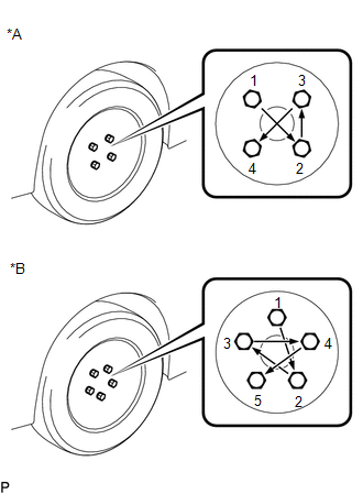
(c) Lower the vehicle then fully tighten the axle hub nuts in the order shown in the illustration.
Torque:
103 N·m {1050 kgf·cm, 76 ft·lbf}
 Installation
INSTALLATION CAUTION / NOTICE / HINT HINT:
Use the same procedure for the RH side and LH side.
The following procedure is for the LH side.
PROCEDURE 1...
 Transmitter Battery
ComponentsCOMPONENTS ILLUSTRATION
*1 MECHANICAL KEY *2 TRANSMITTER BATTERY *3 TRANSMITTER HOUSING CASE *4 TRANSMITTER HOUSING COVER RemovalREMOVAL CAUTION / NOTICE / HINT NOTICE: Take extra care when handling these precision electronic components...
Other information:
Toyota Yaris XP210 (2020-2026) Reapir and Service Manual: Differential Oil Temperature Sensor
ComponentsCOMPONENTS ILLUSTRATION *1 TEMPERATURE SENSOR *2 GASKET *3 TAIL EXHAUST PIPE ASSEMBLY - - Tightening torque for "Major areas involving basic vehicle performance such as moving/turning/stopping" : N*m (kgf*cm, ft...
Toyota Yaris XP210 (2020-2026) Owner's Manual: Bluetooth® Audio Device Information Display
When connecting a Bluetooth® audio device, the unit searches the following information from the database stored in the vehicle and it is displayed on the screen. The database information stored in this device uses database information in the Gracenote® music recognitions service...
Categories
- Manuals Home
- Toyota Yaris Owners Manual
- Toyota Yaris Service Manual
- Headlights
- Brake System Control Module "A" System Voltage System Voltage Low (C137BA2)
- Auto Lock/Unlock Function
- New on site
- Most important about car
Break-In Period
No special break-in is necessary, but a few precautions in the first 600 miles (1,000 km) may add to the performance, economy, and life of the vehicle.
Do not race the engine. Do not maintain one constant speed, either slow or fast, for a long period of time. Do not drive constantly at full-throttle or high engine rpm for extended periods of time. Avoid unnecessary hard stops. Avoid full-throttle starts.