Toyota Yaris: Maintenance / Transmitter Battery
Components
COMPONENTS
ILLUSTRATION
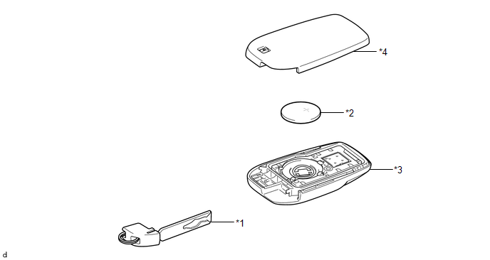
| *1 | MECHANICAL KEY | *2 | TRANSMITTER BATTERY |
| *3 | TRANSMITTER HOUSING CASE | *4 | TRANSMITTER HOUSING COVER |
Removal
REMOVAL
CAUTION / NOTICE / HINT
NOTICE:
Take extra care when handling these precision electronic components.
PROCEDURE
1. REMOVE TRANSMITTER BATTERY
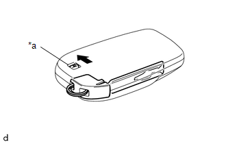
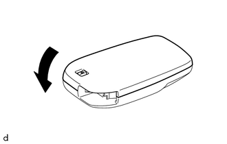
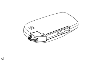
| (a) Slide the release hook knob to remove the mechanical key. |
|
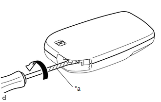
| (b) Using a screwdriver with its tip wrapped in protective tape, pry apart the transmitter housing cover. NOTICE: Do not use excessive force when prying apart the transmitter housing cover. |
|
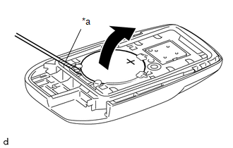
| (c) Using a screwdriver with its tip wrapped in protective tape, remove the transmitter battery. NOTICE:
|
|
Installation
INSTALLATION
CAUTION / NOTICE / HINT
NOTICE:
Take extra care when handling these precision electronic components.
PROCEDURE
1. INSTALL TRANSMITTER BATTERY
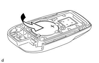
| (a) Install a new transmitter battery with the positive (+) side facing upward. NOTICE:
|
|
| (b) Install the transmitter housing cover by pressing down on it as shown in the illustration. |
|
| (c) Insert the mechanical key into the transmitter. |
|
(d) Press one of the transmitter switches and check that the LED illuminates.
OK:
Transmitter LED illuminates when a switch is pressed.
 Tire And Wheel
ComponentsCOMPONENTS ILLUSTRATION
*1 WHEEL ASSEMBLY *2 AXLE HUB NUT
Tightening torque for "Major areas involving basic vehicle performance such as moving/turning/stopping" : N*m (kgf*cm, ft...
 Setup
Setup
..
Other information:
Toyota Yaris XP210 (2020-2026) Reapir and Service Manual: Security Indicator Light Does not Blink
DESCRIPTION The certification ECU (smart key ECU assembly) blinks the security indicator light (combination meter assembly) when the immobiliser is set (engine switch off). The certification ECU (smart key ECU assembly) receives the security indicator light signal from the main body ECU (multiplex network body ECU) via CAN communication when the theft deterrent system is in the arming preparation state or alarm sounding state...
Toyota Yaris XP210 (2020-2026) Reapir and Service Manual: Diagnostic Trouble Code Chart
D..
Categories
- Manuals Home
- Toyota Yaris Owners Manual
- Toyota Yaris Service Manual
- Key Battery Replacement
- Diagnostic Trouble Code Chart
- Immobilizer System
- New on site
- Most important about car
Supplemental Restraint System (SRS) Precautions
The front and side supplemental restraint systems (SRS) include different types of air bags. Please verify the different types of air bags which are equipped on your vehicle by locating the “SRS AIRBAG” location indicators. These indicators are visible in the area where the air bags are installed.
The air bags are installed in the following locations:
The steering wheel hub (driver air bag) The front passenger dashboard (front passenger air bag) The outboard sides of the front seatbacks (side air bags) The front and rear window pillars, and the roof edge along both sides (curtain air bags)
