Toyota Yaris: Power Steering Ecu / Installation
INSTALLATION
CAUTION / NOTICE / HINT
NOTICE:
After performing the update ECU security key procedure, make sure to perform the initialization procedure for when the cable has been disconnected and reconnected to the negative (-) auxiliary battery terminal.
PROCEDURE
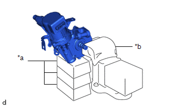
1. INSTALL ELECTRIC POWER STEERING MOTOR SHAFT DAMPER
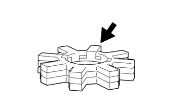
 | Grease |
(a) Apply grease to a new electric power steering motor shaft damper.
NOTICE:
First wipe off the existing grease from the serrated part, and then apply the dedicated grease supplied with a new power steering ECU assembly or electric power steering column sub-assembly.
| (b) Install the electric power steering motor shaft damper to the electric power steering column sub-assembly. |
|
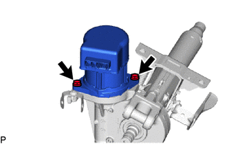
2. INSTALL POWER STEERING ECU ASSEMBLY
NOTICE:
- Do not drop the power steering ECU assembly, strike it with tools or subject it to impacts.
- If the power steering ECU assembly is subjected to an impact, replace it with a new one.
- Do not pull the wire harness of the electric power steering column sub-assembly.
- Do not allow any moisture to come into contact with the power steering ECU assembly.
- Do not loosen any bolts not mentioned in the procedure.
- Do not allow any foreign matter to contaminate the power steering ECU assembly.
| (a) Temporarily install the power steering ECU assembly to the electric power steering column sub-assembly with the 2 bolts. NOTICE: When temporarily installing the 2 bolts to the power steering ECU assembly, do not tighten them all the way down. |
|
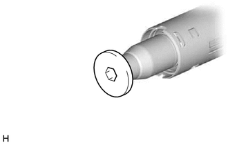
| (b) Using a 10 mm hexagon socket wrench, install the steering wheel assembly set bolt to the steering main shaft. NOTICE: Do not apply excessive torque to the steering wheel assembly set bolt by using a tool such as an impact wrench. HINT: The steering wheel assembly set bolt is used for turning the steering main shaft during inspection of the steering main shaft rotating torque. Remove the steering wheel assembly set bolt after performing this inspection. |
|
| (c) Secure the steering column assembly in a vise using aluminum plates, cloths and wooden blocks. NOTICE:
|
|
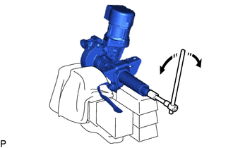
 | Rotate |
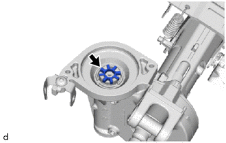
(d) Rotate the steering main shaft 180 degrees counterclockwise and then 180 degrees clockwise at a speed of 60 rpm, and repeat 2 to 3 times to center the axis of the power steering ECU assembly. [*1]
(e) Tighten the 2 bolts. [*2]
Torque:
18.5 N·m {189 kgf·cm, 14 ft·lbf}
(f) Using a torque wrench, measure the turning torque of the steering main shaft.
Preload:
1.0 to 2.2 N*m (11 to 22 kgf*cm, 9 to 19 in.*lbf)
NOTICE:
Ensure that there is no abnormal resistance during rotation.
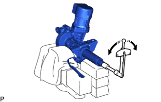
 | Turn |
(g) If the turning torque is not as specified, loosen the 2 bolts and repeat steps [*1] and [*2] to recenter the axis of the power steering ECU assembly.
(h) Remove the steering wheel assembly set bolt.
(i) Connect the connector.
3. INSTALL STEERING LOCK ACTUATOR OR UPPER BRACKET ASSEMBLY
Click here

4. ALIGN FRONT WHEELS FACING STRAIGHT AHEAD
5. INSTALL STEERING COLUMN ASSEMBLY
Click here

6. INSTALL NO. 2 STEERING INTERMEDIATE SHAFT ASSEMBLY
Click here

7. CONNECT NO. 2 STEERING INTERMEDIATE SHAFT ASSEMBLY
Click here

8. INSTALL COLUMN HOLE COVER SILENCER SHEET
Click here

9. INSTALL NO. 1 AIR DUCT
Click here

10. INSTALL STOP LIGHT SWITCH ASSEMBLY
Click here

11. INSTALL LOWER INSTRUMENT PANEL FINISH PANEL ASSEMBLY
Click here

12. CONNECT HOOD LOCK CONTROL LEVER SUB-ASSEMBLY
Click here

13. INSTALL NO. 1 INSTRUMENT SIDE PANEL
Click here

14. INSTALL FRONT DOOR OPENING TRIM WEATHERSTRIP LH
Click here

15. INSTALL NO. 1 INSTRUMENT PANEL UNDER COVER SUB-ASSEMBLY
Click here

16. INSTALL COWL SIDE TRIM BOARD LH
Click here

17. INSTALL FRONT DOOR SCUFF PLATE LH
Click here

18. INSTALL CONSOLE BOX ASSEMBLY
Click here

19. INSTALL TURN SIGNAL SWITCH ASSEMBLY WITH SPIRAL CABLE SUB-ASSEMBLY
Click here

20. INSTALL UPPER STEERING COLUMN COVER
Click here

21. INSTALL LOWER STEERING COLUMN COVER
Click here

22. ALIGN FRONT WHEELS FACING STRAIGHT AHEAD
23. ADJUST SPIRAL CABLE WITH SENSOR SUB-ASSEMBLY
Click here

24. INSTALL STEERING WHEEL ASSEMBLY
Click here

25. INSTALL HORN BUTTON ASSEMBLY
Click here

26. CONNECT CABLE TO NEGATIVE AUXILIARY BATTERY TERMINAL
Click here

27. UPDATE ECU SECURITY KEY
Click here

28. PERFORM POWER STEERING ECU INITIAL SETTING
Click here

29. INSPECT HORN BUTTON ASSEMBLY
(a) Make sure that the horn sounds.
If the horn does not sound, inspect the horn system.
Click here

30. PERFORM CODE REGISTRATION
HINT:
When replacing the steering lock actuator or upper bracket assembly, perform code registration.
Click here

31. CHECK STEERING WHEEL CENTER POINT
Click here

32. PERFORM DIAGNOSTIC SYSTEM CHECK
Click here

33. INSPECT SRS WARNING LIGHT
Click here

34. INITIALIZATION AFTER RECONNECTING AUXILIARY BATTERY TERMINAL
HINT:
When disconnecting and reconnecting the auxiliary battery, there is an automatic learning function that completes learning when the respective system is used.
Click here

 Removal
REMOVAL CAUTION / NOTICE / HINT The necessary procedures (adjustment, calibration, initialization, or registration) that must be performed after parts are removed and installed, or replaced during the power steering ECU assembly removal/installation are shown below...

Other information:
Toyota Yaris XP210 (2020-2026) Reapir and Service Manual: Power Source Mode does not Change to ON (IG)
DESCRIPTION If the engine switch is pressed with the electrical key transmitter sub-assembly in the cabin, the certification ECU (smart key ECU assembly) receives a signal and changes the power source mode. Related Data List and Active Test Items Problem Symptom Data List and Active Test Power source mode does not change to on (IG) but does change to on (ACC) Power Source Control Power Supply Condition IGP Relay Circuit (Outside) Monitor IGP Relay Circuit (Inside) Monitor IGR Relay Circuit (Outside) Monitor IGR Relay Circuit (Inside) Monitor WIRING DIAGRAM CAUTION / NOTICE / HINT NOTICE: When using the GTS with the ignition switch off, connect the GTS to the DLC3 and turn a courtesy light switch on and off at intervals of 1...
Toyota Yaris XP210 (2020-2026) Reapir and Service Manual: Yaw Rate Sensor Signal Bias Level Out of Range / Zero Adjustment Failure (C006328,C006396)
DESCRIPTION These DTCs are stored when the skid control ECU (brake actuator assembly) receives an internal malfunction signal from the yaw rate and acceleration sensor (airbag sensor assembly). DTC No. Detection Item DTC Detection Condition Trouble Area DTC Output from C006328 Yaw Rate Sensor Signal Bias Level Out of Range / Zero Adjustment Failure With the vehicle stationary, the yaw rate sensor output value is not 0°/s...
Categories
- Manuals Home
- Toyota Yaris Owners Manual
- Toyota Yaris Service Manual
- How to use USB mode
- How to connect USB port/Auxiliary jack
- Key Battery Replacement
- New on site
- Most important about car
Front Seat Belt Pretensioners
The front seat belt pretensioners are designed to deploy in moderate or severe frontal, near frontal collisions.
In addition, the pretensioners operate when a side collision or a rollover accident is detected. The pretensioners operate differently depending on what types of air bags are equipped. For more details about the seat belt pretensioner operation, refer to the SRS Air Bag Deployment Criteria.