Toyota Yaris: Oil Pressure And Temperature Sensor / Installation
INSTALLATION
PROCEDURE
1. INSTALL OIL PRESSURE AND TEMPERATURE SENSOR
| (a) Apply adhesive to 2 or 3 threads of the oil pressure and temperature sensor. Adhesive: Toyota Genuine Adhesive 1344, Three Bond 1344 or equivalent NOTICE:
|
|
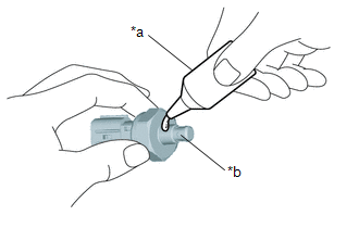
(b) Using a 24 mm deep socket wrench, install the oil pressure and temperature sensor.
Torque:
15 N·m {153 kgf·cm, 11 ft·lbf}
NOTICE:
Do not start the engine within 1 hour of installation.
(c) Connect the oil pressure and temperature sensor connector.
2. INSPECT FOR ENGINE OIL LEAK
Click here

3. INSTALL NO. 1 ENGINE UNDER COVER ASSEMBLY
Click here

 Inspection
INSPECTION PROCEDURE 1. INSPECT OIL PRESSURE AND TEMPERATURE SENSOR (a) Check the oil pressure and temperature sensor output voltage. (1) Apply 5 V between terminals 3 (VC) and 2 (GND)...
 Oil Pump
..
Other information:
Toyota Yaris XP210 (2020-2026) Reapir and Service Manual: Ea67f Manual Transaxle Oil
ComponentsCOMPONENTS ILLUSTRATION *1 NO. 1 ENGINE UNDER COVER ASSEMBLY *2 ENGINE UNDER COVER LH *3 MANUAL TRANSMISSION FILLER PLUG *4 MANUAL TRANSMISSION DRAIN PLUG *5 GASKET - - N*m (kgf*cm, ft.*lbf): Specified torque ● Non-reusable part ReplacementREPLACEMENT PROCEDURE 1...
Toyota Yaris XP210 (2020-2026) Reapir and Service Manual: Entry Exterior Alarm does not Sound
DESCRIPTION The smart key system (for Entry Function) uses the wireless door lock buzzer to perform various vehicle exterior warnings. When the conditions of each warning are met, the certification ECU (smart key ECU assembly) sends a buzzer activation request signal to the main body ECU (multiplex network body ECU) via CAN communication and the buzzer sounds...
Categories
- Manuals Home
- Toyota Yaris Owners Manual
- Toyota Yaris Service Manual
- Key Battery Replacement
- Engine Start Function When Key Battery is Dead
- Fuel Gauge
- New on site
- Most important about car
Fuel Gauge
The fuel gauge shows approximately how much fuel is remaining in the tank when the ignition is switched ON. We recommend keeping the tank over 1/4 full.
