Toyota Yaris: Oil Pressure And Temperature Sensor / Inspection
INSPECTION
PROCEDURE
1. INSPECT OIL PRESSURE AND TEMPERATURE SENSOR
(a) Check the oil pressure and temperature sensor output voltage.
| (1) Apply 5 V between terminals 3 (VC) and 2 (GND). NOTICE:
HINT: If a stable power supply is not available, connect 4 nickel-metal hydride batteries (1.2 V each) or equivalent in series. |
|
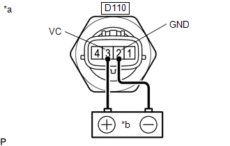
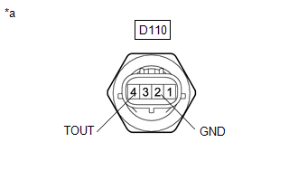
| (b) Measure the voltage between terminals. Standard Voltage:
*: The output voltage changes depending on the voltage applied to the terminals. If the result is not as specified, replace the oil pressure and temperature sensor. |
|
 Removal
REMOVAL PROCEDURE 1. REMOVE NO. 1 ENGINE UNDER COVER ASSEMBLY Click here
2. REMOVE OIL PRESSURE AND TEMPERATURE SENSOR (a) Disconnect the oil pressure and temperature sensor connector...
 Installation
INSTALLATION PROCEDURE 1. INSTALL OIL PRESSURE AND TEMPERATURE SENSOR (a) Apply adhesive to 2 or 3 threads of the oil pressure and temperature sensor...
Other information:
Toyota Yaris XP210 (2020-2026) Reapir and Service Manual: Drive Shaft System
PrecautionPRECAUTION NOTICE OF REMOVING AND INSTALLING FRONT DRIVE SHAFT ASSEMBLY RH (a) When removing and installing the front drive shaft assembly RH, be sure to first drain all the transaxle oil and transfer oil. If removal and installation are carried out without draining these oils, the transfer oil will flow into the transaxle side...
Toyota Yaris XP210 (2020-2026) Reapir and Service Manual: Inspection
INSPECTION PROCEDURE 1. INSPECT REAR DRIVE SHAFT ASSEMBLY (a) Check that there is no excessive play in the radial direction of the outboard joint. (b) Check that the inboard joint slides smoothly in the thrust direction. (c) Check that there is no excessive play in the radial direction of the inboard joint...
Categories
- Manuals Home
- Toyota Yaris Owners Manual
- Toyota Yaris Service Manual
- Brake System Control Module "A" System Voltage System Voltage Low (C137BA2)
- Headlights
- Fuse Panel Description
- New on site
- Most important about car
Fuel-Filler Lid and Cap
WARNING
When removing the fuel-filler cap, loosen the cap slightly and wait for any hissing to stop, then remove it
Fuel spray is dangerous. Fuel can burn skin and eyes and cause illness if ingested. Fuel spray is released when there is pressure in the fuel tank and the fuel-filler cap is removed too quickly.