Toyota Yaris: Camshaft Position Sensor / Installation
INSTALLATION
PROCEDURE
1. INSTALL CAMSHAFT POSITION SENSOR (for Intake Side)
| (a) Clean the O-ring groove of the camshaft position sensor. NOTICE: Make sure the O-ring groove is free of foreign matter. |
|
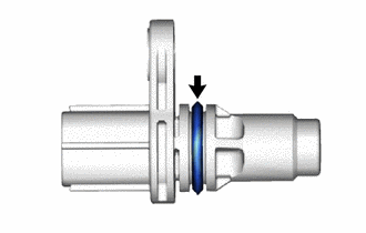
(b) Install a new O-ring to the camshaft position sensor.
NOTICE:
Set the O-ring on the tip of the camshaft position sensor and roll it into the O-ring groove with bare hands to install it.
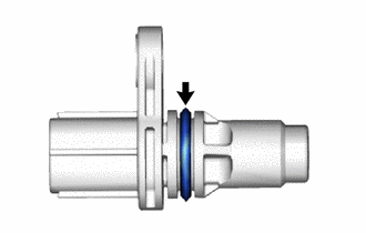
(c) Check if the O-ring is twisted.
| (d) Install the camshaft position sensor to the cylinder head cover sub-assembly with a new bolt. Torque: 10 N·m {102 kgf·cm, 7 ft·lbf} NOTICE:
|
|
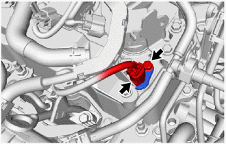
(e) Connect the camshaft position sensor connector.
2. INSTALL CAMSHAFT POSITION SENSOR (for Exhaust Side)
| (a) Clean the O-ring groove of the camshaft position sensor. NOTICE: Make sure the O-ring groove is free of foreign matter. |
|
(b) Install a new O-ring to the camshaft position sensor.
NOTICE:
Set the O-ring on the tip of the camshaft position sensor and roll it into the O-ring groove with bare hands to install it.
(c) Check if the O-ring is twisted.
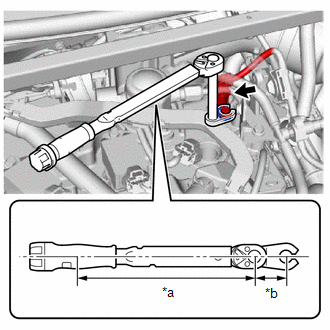
| (d) Using a 10 mm union nut wrench, install the camshaft position sensor to the cylinder head cover sub-assembly with a new bolt. Torque: Specified Tightening Torque : 10 N·m {102 kgf·cm, 7 ft·lbf} NOTICE:
HINT:
|
|

(e) Connect the camshaft position sensor connector.
3. INSTALL IGNITION COIL ASSEMBLY
(a) Install the bolt and ignition coil assembly.
Torque:
10 N·m {102 kgf·cm}
(b) Connect the ignition coil assembly connector.
4. INSTALL ENGINE WIRE
(a) Install the bolt and engine wire.
Torque:
10 N·m {102 kgf·cm}
5. INSPECT FOR ENGINE OIL LEAK
Click here

 Removal
REMOVAL PROCEDURE 1. SEPARATE ENGINE WIRE (a) Remove the bolt and engine wire.
2. REMOVE IGNITION COIL ASSEMBLY (a) Disconnect the ignition coil assembly connector...
 Crankshaft Position Sensor
ComponentsCOMPONENTS ILLUSTRATION
*1 CRANKSHAFT POSITION SENSOR *2 O-RING
Tightening torque for "Major areas involving basic vehicle performance such as moving/turning/stopping" : N*m (kgf*cm, ft...
Other information:
Toyota Yaris XP210 (2020-2026) Reapir and Service Manual: Replacement
REPLACEMENT PROCEDURE 1. REPLACE RING PIN NOTICE: It is not necessary to remove the ring pins unless they are being replaced. (a) Remove the 10 ring pins. (b) Using a plastic hammer, install 10 new ring pins. *a 14 mm (0.551 in.) *b 12 mm (0...
Toyota Yaris XP210 (2020-2026) Reapir and Service Manual: Diagnostic Trouble Code Chart
D..
Categories
- Manuals Home
- Toyota Yaris Owners Manual
- Toyota Yaris Service Manual
- Key Battery Replacement
- Power Integration No.1 System Missing Message (B235287,B235587,B235787-B235987)
- How to use USB mode
- New on site
- Most important about car
Front Seat Belt Pretensioners
The front seat belt pretensioners are designed to deploy in moderate or severe frontal, near frontal collisions.
In addition, the pretensioners operate when a side collision or a rollover accident is detected. The pretensioners operate differently depending on what types of air bags are equipped. For more details about the seat belt pretensioner operation, refer to the SRS Air Bag Deployment Criteria.